
Introduction
Perhaps the most popular board in the Arduino line-up is the Arduino UNO. There are other boards like the Arduino Nano and the Arduino Mega, but UNO has been the go-to board for quick prototyping, Arduino Projects and DIY Projects.
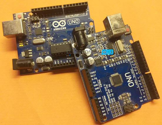
Arduino UNO is based on ATmega328P Microcontroller, an 8-bit AVR Architecture based MCU from ATMEL. Arduino UNO comes in two variants: one consists of a 28-pin DIP Microcontroller while the other consists of 32 lead Quad Flat Package Microcontroller.
Arduino UNO Board Layout
The following image shows the layout of a typical Arduino UNO board. All the components are placed on the top side of the PCB.
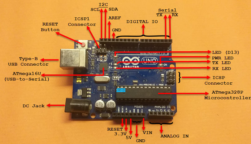
As you can notice, there is a Type-B USB connector on the left short edge of the board, which is used for powering on the board as well as programming the Microcontroller. There is also a 2.1 mm DC jack to provide external power supply.
Apart from that, the layout of Arduino UNO is very much self-explanatory.
I will discuss about the pins of Arduino UNO in the Arduino UNO Pinout Section.
Technical Specifications of Arduino UNO
As Arduino UNO is based on ATmega328P Microcontroller, the technical specifications of Arduino UNO are mostly related to the ATmega328P MCU. But none the less, let me give you a brief overview about some important specifications of Arduino UNO.
| MCU | ATmega328P |
| Architecture | AVR |
| Operating Voltage | 5V |
| Input Voltage | 6V – 20V (limit)7V – 12V (recommended) |
| Clock Speed | 16 MHz |
| Flash Memory | 32 KB (2 KB of this used by bootloader) |
| SRAM | 2 KB |
| EEPROM | 1 KB |
| Digital IO Pins | 24 (of which 6 can produce PWM) |
| Analog Input Pins | 6 |
How to power up the Arduino UNO?
There are a couple of ways in which you can power the UNO board. The first and easy way is using the Type-B USB Connector. The next way is to provide an unregulated supply in the range of 6V to 20V to VIN pin of the UNO (Pin number 26).
You can also supply the unregulated supply through the 2.1mm DC Jack, in which case, you can access the supplied voltage through the VIN Pin.
What are Different Memories of Arduino UNO?
Strictly speaking, this is specific to the MCU i.e., ATmega328P, used on the Arduino UNO Board. There are three different memories available in ATmega328P. They are:
- 32 KB of Flash Memory
- 2 KB of SRAM
- 1 KB of EEPROM
- 0.5 KB of the Flash Memory is used by the bootloader code.
What are the Input and Output Pins of Arduino UNO?
Of the 32 pins available on the UNO board, 22 pins are associated with input and output. In that 14 pins (D0 to D13) are true digital IO pins, which can be configured as per you application using pinMode(), digitalWrite() and digitalRead() functions.
All these Digital IO pins are capable of sourcing or sinking 20mA of current (maximum 40mA is allowed). An additional feature of the Digital IO pins is the availability of internal pull-up resistor (which is not connected by default).
The value of the internal pull-up resistor will be in the range of 20KΩ to 50KΩ.
There are also 6 Analog Input Pins (A0 to A5). All the analog input pins provide a 10-bit resolution ADC feature, which can be read using analogRead() function.
An important point about Analog Input pins is that they can be configured as Digital IO pins, if required.
Digital IO pins 3, 5, 6, 9, 10 and 11 are capable of producing 8-bit PWM Signals. You can use analogWrite() function for this.
What Communication Interfaces are available on Arduino UNO?
Arduino UNO supports three different types of communication interfaces. They are:
- Serial
- I2C or I2C
- SPI
Perhaps the most common communication interface in the Arduino universe is the Serial Communication. In fact, the Arduino boards (UNO or Nano or Mega) are programmed using the serial communication.
Digital IO pins 0 and 1 are used as Serial RX and TX pins to receive and transmit serial data. These pins are connected to the serial pins of the on-board USB to Serial Converter IC.
Analog Input Pins A4 and A5 have alternative functions. They can be configured as SDA (A4) and SCL (A5) to support I2C or I2C or Two Wire Interface (TWI) communication.
The final communication interface is the SPI. Digital IO Pins 10, 11 12 and 13 can be configured as SPI pins SS, MOSI, MISO and SCK respectively.
Any additional features?
There is an on-board LED connected to digital IO pin 13. Use this LED to perform Blinky operations. The reference voltage for the internal ADC is by default set to 5V. But using the AREF pin, you can manually set the upper limit of the ADC.
Using the IOREF pin, you can set the reference voltage for Microcontroller operations.
To reset the microcontroller, you can use the on-board RESET button.
Although you can program the Arduino UNO using the USB cable, there is a provision to program the MCU using the In-Circuit Serial Programming (ICSP) interface.
The UART bootloader, which is preloaded in to the ATmega328P microcontroller, enables programming through serial interface. But ICSP doesn’t need any bootloader.
You can program Arduino UNO using ISCP or use the ISCP of Arduino UNO to program other Arduino Boards.
Digital IO Pins 2 and 3 can be configured as External Interrupts Pins INT0 and INT1 respectively. Use attachInterrupt() function to configure the Interrupt for rising edge, falling edge or level change on the pin.
Arduino UNO Pinout
Now that we have seen a little bit about Arduino UNO and its important features and specifications, let us dive into the Arduino UNO Pinout. The following image shows the complete pinout of Arduino UNO Board.
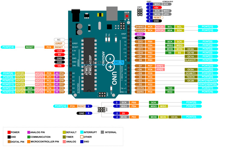
As you can see from the image, I described each pin of the Arduino UNO with its microcontroller equivalent pin, alternative functions, default functionality and other additional features.
For higher resolution image, click here.
Pin Description
For pin description of Arduino UNO, let us assume some basic numbering. Let the numbering begin with the RX Pin (D0). So, RX is Pin 1, TX is Pin 2, D2 is Pin 3 and so on.
On the other side, NC is Pin 19, IOREF is Pin 20 etc. Overall, there are 32 pins on the Arduino UNO Board.
With this information, let us now see the pin description of Arduino UNO.
| Pin Number | Pin Name | Description | Alternative Functions |
| 1 | RX / D0 | Digital IO Pin 0Serial RX Pin | Generally used as RX |
| 2 | TX / D1 | Digital IO Pin 1Serial TX Pin | Generally used as TX |
| 3 | D2 | Digital IO Pin 2 | |
| 4 | D3 | Digital IO Pin 3 | Timer (OC2B) |
| 5 | D4 | Digital IO Pin 4 | Timer (T0/XCK) |
| 6 | D5 | Digital IO Pin 5 | Timer (OC0B/T1) |
| 7 | D6 | Digital IO Pin 6 | |
| 8 | D7 | Digital IO Pin 7 | |
| 9 | D8 | Digital IO Pin 8 | Timer (CLK0/ICP1) |
| 10 | D9 | Digital IO Pin 9 | Timer (OC1A) |
| 11 | D10 | Digital IO Pin 10 | Timer (OC1B) |
| 12 | D11 | Digital IO Pin 11 | SPI (MOSI) Timer (OC2A) |
| 13 | D12 | Digital IO Pin 12 | SPI (MISO) |
| 14 | D13 | Digital IO Pin 13 | SPI (SCK) |
| 15 | GND | Ground | |
| 16 | AREF | Analog Reference | |
| 17 | SDA / D18 | Digital IO Pin 18 | I2C Data Pin |
| 18 | SCL / D19 | Digital IO Pin 19 | I2C Clock Pin |
| 19 | NC | Not Connected | |
| 20 | IOREF | Voltage Reference | |
| 21 | RESET | Reset (Active LOW) | |
| 22 | 3V3 | Power | |
| 23 | 5V | +5V Output from regulator or +5V regulated Input | |
| 24 | GND | Ground | |
| 25 | GND | Ground | |
| 26 | VIN | Unregulated Supply | |
| 27 | A0 | Analog Input 0 | Digital IO Pin 14 |
| 28 | A1 | Analog Input 1 | Digital IO Pin 15 |
| 29 | A2 | Analog Input 2 | Digital IO Pin 16 |
| 30 | A3 | Analog Input 3 | Digital IO Pin 17 |
| 31 | A4 | Analog Input 4 | Digital IO Pin 18 I2C (SDA) |
| 32 | A5 | Analog Input 5 | Digital IO Pin 19 I2C (SCL) |
The following table describes the pins of the ICSP Connector.
| MISO | Master In Slave Out (Input or Output) |
| 5V | Supply |
| SCK | Clock (from Master to Slave) |
| MOSI | Master Out Slave In (Input or Output) |
| RESET | Reset (Active LOW) |
| GND | Ground |
There is also a similar ICSP connector known as ICSP1 associated with the ATmega16U Microcontroller. For more information on this connector, take a look at the Arduino UNO Pinout image.
Conclusion
This was a brief overview on Arduino UNO board layout, technical specifications, important features and most importantly the complete Arduino UNO Pinout information.