In this getting started guide you’ll learn how to read digital inputs like a button switch and control digital outputs like an LED using the ESP32 with Arduino IDE.

Prerequisites
We’ll program the ESP32 using Arduino IDE. So, make sure you have the ESP32 boards add-on installed before proceeding:
ESP32 Control Digital Outputs
First, you need set the GPIO you want to control as an OUTPUT. Use the pinMode() function as follows:
pinMode(GPIO, OUTPUT);To control a digital output you just need to use the digitalWrite() function, that accepts as arguments, the GPIO (int number) you are referring to, and the state, either HIGH or LOW.
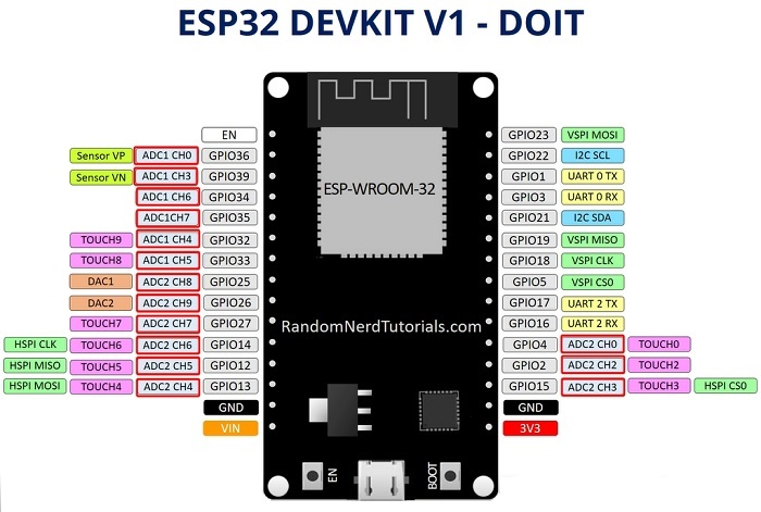
digitalWrite(GPIO, STATE);All GPIOs can be used as outputs except GPIOs 6 to 11 (connected to the integrated SPI flash) and GPIOs 34, 35, 36 and 39 (input only GPIOs);
ESP32 Read Digital Inputs
First, set the GPIO you want to read as INPUT, using the pinMode() function as follows:
pinMode(GPIO, INPUT);To read a digital input, like a button, you use the digitalRead() function, that accepts as argument, the GPIO (int number) you are referring to.
digitalRead(GPIO);All ESP32 GPIOs can be used as inputs, except GPIOs 6 to 11 (connected to the integrated SPI flash).
Learn more about the ESP32 GPIOs: ESP32 GPIO Reference Guide
Project Example
To show you how to use digital inputs and digital outputs, we’ll build a simple project example with a pushbutton and an LED. We’ll read the state of the pushbutton and light up the LED accordingly as illustrated in the following figure.

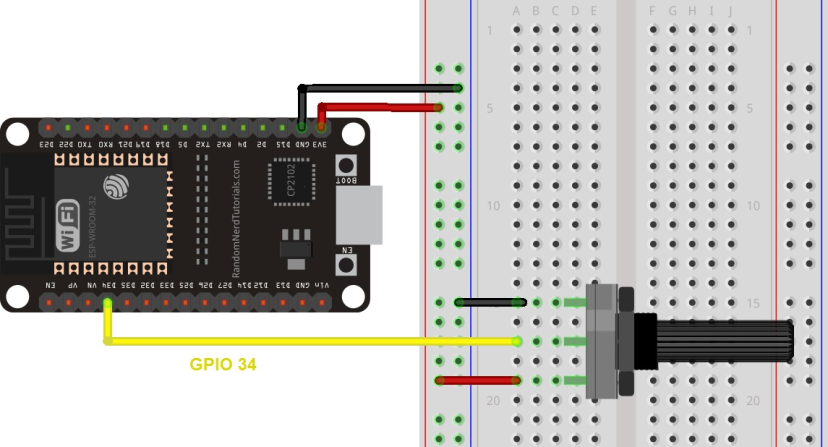
Schematic Diagram
Before proceeding, you need to assemble a circuit with an LED and a pushbutton. We’ll connect the LED to GPIO 5 and the pushbutton to GPIO 4.
Parts Required
Here’s a list of the parts to you need to build the circuit:
- ESP32 (read Best ESP32 Dev Boards)
- 5 mm LED
- 330 Ohm resistor
- Pushbutton
- 10k Ohm resistor
- Breadboard
- Jumper wires
You can use the preceding links or go directly to MakerAdvisor.com/tools to find all the parts for your projects at the best price!

Code
Copy the following code to your Arduino IDE.
// Complete Instructions: https://RandomNerdTutorials.com/esp32-digital-inputs-outputs-arduino/

// set pin numbers
const int buttonPin = 4;  // the number of the pushbutton pin
const int ledPin =  5;    // the number of the LED pin

// variable for storing the pushbutton status
int buttonState = 0;

void setup() {
  Serial.begin(115200);
  // initialize the pushbutton pin as an input
  pinMode(buttonPin, INPUT);
  // initialize the LED pin as an output
  pinMode(ledPin, OUTPUT);
}

void loop() {
  // read the state of the pushbutton value
  buttonState = digitalRead(buttonPin);
  Serial.println(buttonState);
  // check if the pushbutton is pressed.
  // if it is, the buttonState is HIGH
  if (buttonState == HIGH) {
    // turn LED on
    digitalWrite(ledPin, HIGH);
  } else {
    // turn LED off
    digitalWrite(ledPin, LOW);
  }
}
How the Code Works
In the following two lines, you create variables to assign pins:
const int buttonPin = 4;
const int ledPin = 5;
The button is connected to GPIO 4 and the LED is connected to GPIO 5. When using the Arduino IDE with the ESP32, 4 corresponds to GPIO 4 and 5 corresponds to GPIO 5.
Next, you create a variable to hold the button state. By default, it’s 0 (not pressed).
int buttonState = 0;In the setup(), you initialize the button as an INPUT, and the LED as an OUTPUT. For that, you use the pinMode() function that accepts the pin you are referring to, and the mode: INPUT or OUTPUT.
pinMode(buttonPin, INPUT);
pinMode(ledPin, OUTPUT);
In the loop() is where you read the button state and set the LED accordingly.
In the next line, you read the button state and save it in the buttonState variable. As we’ve seen previously, you use the digitalRead() function.
buttonState = digitalRead(buttonPin);The following if statement, checks whether the button state is HIGH. If it is, it turns the LED on using the digitalWrite() function that accepts as argument the ledPin, and the state HIGH.
if (buttonState == HIGH) {
  digitalWrite(ledPin, HIGH);
}
If the button state is not HIGH, you set the LED off. Just set LOW as a second argument to in the digitalWrite() function.
else {
  digitalWrite(ledPin, LOW);
}
Uploading the Code
Before clicking the upload button, go to Tools > Board, and select the board you’re using. In my case, it’s the DOIT ESP32 DEVKIT V1 board.
Go to Tools > Port and select the COM port the ESP32 is connected to. Then, press the upload button and wait for the “Done uploading” message.

If you see a lot of dots (…__…__) on the debugging window and the “Failed to connect to ESP32: Timed out waiting for packet header” message, that means you need to press the ESP32 on-board BOOT button after the dots start appearing.
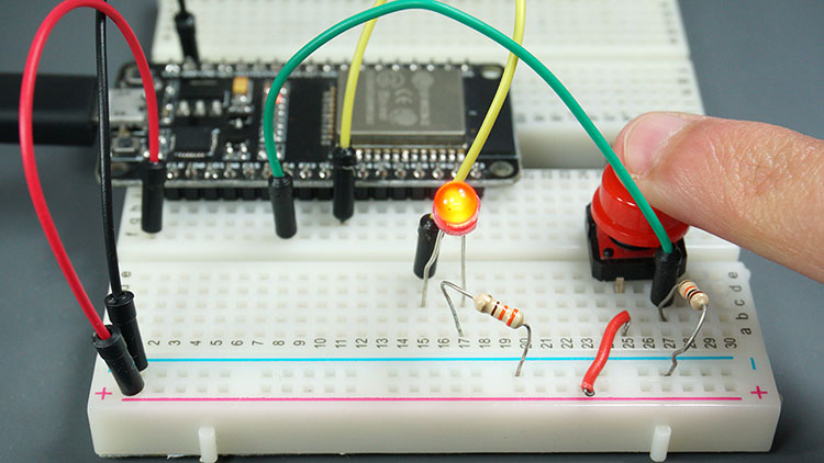
Demonstration
After uploading the code, test your circuit. Your LED should light up when you press the pushbutton:

And turn off when you release it:

Wrapping Up
With this getting started guide, you’ve learned how to read digital inputs and control digital outputs with the ESP32 using Arduino IDE.
If you want to learn how to read analog inputs, or output PWM signals, read the following guides:
You may also find useful taking a look at the ESP32 GPIO Reference that shows how to use the ESP32 GPIOs and its functions.
Finally, if you want to learn more about the ESP32, take a look at our resources:
// set pin numbers
const int buttonPin1 =34; // the number of the pushbutton pin
const int buttonPin2 = 35;
const int buttonPin3 = 32;
const int buttonPin4 = 33;

const int ledPin1 = 23; // the number of the LED pin
const int ledPin2 = 22;
const int ledPin3 = 1;
const int ledPin4 = 3;

// variable for storing the pushbutton status
int buttonState1 = 0;
int buttonState2 = 0;
int buttonState3 = 0;
int buttonState4 = 0;

void setup() {
Serial.begin(115200);
// initialize the pushbutton pin as an input
pinMode(buttonPin1, INPUT);
pinMode(buttonPin2, INPUT);
pinMode(buttonPin3, INPUT);
pinMode(buttonPin4, INPUT);
// initialize the LED pin as an output
pinMode(ledPin1, OUTPUT);
pinMode(ledPin2, OUTPUT);
pinMode(ledPin3, OUTPUT);
pinMode(ledPin4, OUTPUT);
}

void loop() {
// read the state of the pushbutton value
buttonState1 = digitalRead(buttonPin1);
buttonState2 = digitalRead(buttonPin2);
buttonState3 = digitalRead(buttonPin3);
buttonState4 = digitalRead(buttonPin4);


if (buttonState1 == HIGH) {
// turn LED on
digitalWrite(ledPin1, HIGH);
}
else {
// turn LED off
digitalWrite(ledPin1, LOW);}

if (buttonState2 == HIGH) {
// turn LED on
digitalWrite(ledPin2, HIGH);
}
else {
// turn LED off
digitalWrite(ledPin2, LOW);}

if (buttonState3 == HIGH) {
// turn LED on
digitalWrite(ledPin3, HIGH);
}
else {
// turn LED off
digitalWrite(ledPin3, LOW);}

if (buttonState4 == HIGH) {
// turn LED on
digitalWrite(ledPin4, HIGH);
}
else {
// turn LED off
digitalWrite(ledPin4, LOW);}
}Link:https://randomnerdtutorials.com/esp32-digital-inputs-outputs-arduino/