Espressif’s ESP8266 is a Wi-Fi SoC. It has all the bells and whistles for Wi-Fi Network connectivity as well as a very powerful processor. You can build applications using ESP8266 SoC alone but if you have a host MCU, then it can act as a slave as well. There are ESP8266 modules available in the market that you can use in your projects. But before starting, you have to be familiar with the pinout of the SoC as well as the module. So, in this tutorial, we will take a look at the ESP8266 Pinout.
First, we will see the pinout of the ESP8266 SoC. As ESP8266 Wi-Fi Chip is available in several modules, we will also see the pinout of some of those modules.
A Brief Note on ESP8266
The ESP8266 Wi-Fi Module changed the DIY and Hobbyist scene completely. It paved the way for small creators to build IoT and ‘Smart’ things. You can design a Smart Bulb or Smart Relay using ESP8266.
Since it has a powerful microprocessor, you can use it as a standalone device for the processor as well as for Wi-Fi connectivity. But the benefit of ESP8266 is that you can use another processor as the ‘main processing unit’ and use the ESP8266 just as a Wi-Fi chip.
ESP3266 Pinout
We will start understanding the pins of the ESP8266 with the main SoC itself. ESP8266 SoC is available in a 32-pin QFN Package (33 if you consider the center GND pad).
The following image shows the pin layout of the ESP8266 SoC.
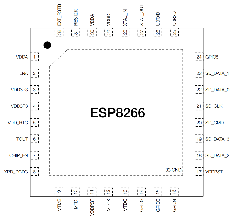
From the above ESP8266 Pinout, you can see that it has only 1 pin (Pin 2 – LNA) for the RF Interface. This shows the level of integration ESP8266 has. Coming to the pins themselves, the following table shows the pin description of all the ESP8266 pins.
| Pin Number | Name | Description |
| 1 | VDDA | Analog Power Supply |
| 2 | LNA | RF Antenna Interface |
| 3 | VDD3P3 | Amplifier Power Supply |
| 4 | VDD3P3 | Amplifier Power Supply |
| 5 | VDD_RTC | NC |
| 6 | TOUT | ADC Pin |
| 7 | CHIP_EN | Chip Enable |
| 8 | XPD_DCDC | Deep Sleep Wakeup |
| 9 | MTMS | GPIO 14 / HSPI_CLK |
| 10 | MTDI | GPIO 12 / HSPI_MISO |
| 11 | VDDPST | Digital IO Power Supply |
| 12 | MTCK | GPIO 13 / HSPI_MOSI / UART0_CTS |
| 13 | MTDO | GPIO 15 / HSPI_CS / UART0_RTS |
| 14 | GPIO 2 | GPIO 2 / UART TXs |
| 15 | GPIO 0 | GPIO 0 / SPI_CS2 |
| 16 | GPIO 4 | GPIO 4 |
| 17 | VDDPST | Digital IO Power Supply |
| 18 | SDIO_DATA_2 | SD_D2 / SPIHD / HSPIHD / GPIO 9 |
| 19 | SDIO_DATA_3 | SD_D3 / SPIWP / HSPIWP / GPIO 10 |
| 20 | SDIO_CMD | SD_CMD / SPI_CS0 / GPIO 11 |
| 21 | SDIO_CLK | SD_CLK / SPI_CLK / GPIO 6 |
| 22 | SDIO_DATA_0 | SD_D0 / SPI_MISO / GPIO 7 |
| 23 | SDIO_DATA_1 | SD_D1 / SPI_MOSI / GPIO 8 |
| 24 | GPIO 5 | GPIO 5 |
| 25 | U0RXD | UART RX / GPIO 3 |
| 26 | U0TXD | UART TX / GPIO 1 / SPI_CS1 |
| 27 | XTAL_OUT | Crystal Oscillator Output |
| 28 | XTAL_IN | Crystal Oscillator Input |
| 29 | VDDD | Analog Power Supply |
| 30 | VDDA | Analog Power Supply |
| 31 | RES12K | Serial Connection with 12 KΩ Resistor |
| 32 | EXT_RSTB | External Reset Signal |
| 33 | GND | Ground Pad |
ESP-01 Pinout
The ESP-01 is one of the simplest ESP8266 modules available today. Ai-Thinker developed this module. It has the main SoC, crystal oscillator, flash memory, and a PCB antenna.
There are also 8 basic pins for programming as well as power. The following image shows the pins layout of ESP-01.
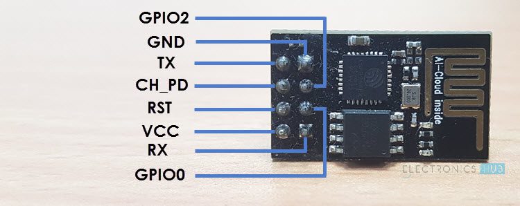
Out of the 33 pins of ESP8266 SoC, the ESP-01 Module
| Pin Name | Pin Function |
| VCC | Power Supply – 3.3V only |
| GND | Ground |
| TX | UART TX |
| RX | UART RX |
| RST | Reset |
| CH_PD | Chip Enable |
| GPIO 0 | GPIO 0 |
| GPIO 2 | GPIO 2 |
NodeMCU Pinout
While ESP-01 is the bare minimum ESP8266 Module, the NodeMCU is a popular compressive solution. It is a proper ESP8266 Development board with all the necessary connectors and components.
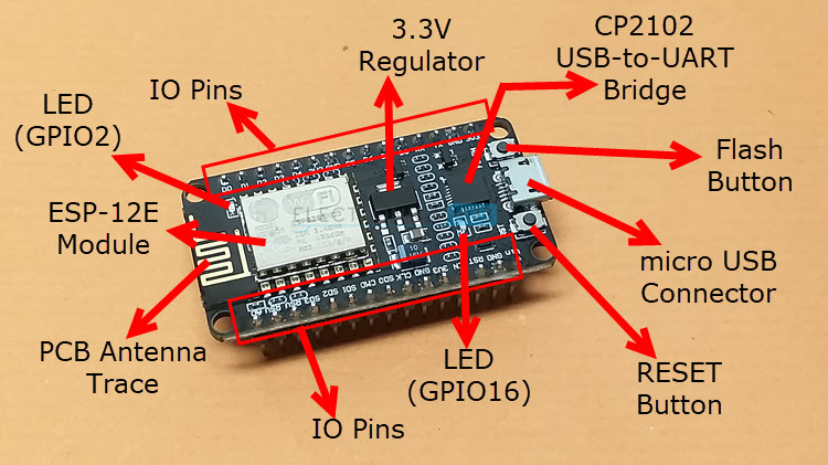
NodeMCU uses ESP-12E Module, again by Ai-Thinker. This module, like the ESP-01, has the SoC, Crystal Oscillator, and Wi-Fi Antenna. All the essential things for ESP8266 SoC. The main difference between ESP-01 and ESP-12E is the number of GPIO Pins.
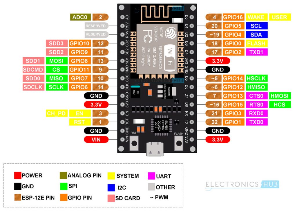
Coming back to NodeMCU, it takes the ESP-12E as the base board and builds a complete system around it. The following image shows the Pinout of NodeMCU.

It has 30 pins. You can see the pin description of all these 30 pins in the following table.
| Pin | Description | Alternate Functions | Default |
| ADC0 | Analog Input | — | ADC0 |
| Reserved | — | — | |
| Reserved | — | — | |
| SDD3 | SDIO Data 3 | GPIO10 | SDD3 |
| SDD2 | SDIO Data 2 | GPIO9 | SDD2 |
| SDD1 | SDIO Data 1 | GPIO8 | SDD1 |
| SDDCMD | SDIO CMD | GPIO11 | SDDCMD |
| SDD0 | SDIO Data 0 | GPIO7 | SDD0 |
| SDCLK | SDIO CLK | GPIO6 | SDCLK |
| GND | Ground | — | — |
| 3.3V | 3.3V Output | — | — |
| EN | Chip Enable (Active HIGH) | — | — |
| RST | Reset (Active LOW) | — | — |
| GND | Ground | — | — |
| VIN | 5V Input to 3.3V Regulator | — | — |
| 3.3V | 3.3V Output | — | — |
| GND | Ground | — | — |
| TXD0 | UART0 TXD | GPIO1 | TXD0 |
| RXD0 | USRT0 RXD | GPIO3 | RXD0 |
| GPIO15 | GPIO15 | HSPI_CS / RTS0 | GPIO15 |
| GPIO13 | GPIO13 | HSPI_MOSI / CTS0 | GPIO13 |
| GPIO12 | GPIO12 | HSPI_MISO | GPIO12 |
| GPIO14 | GPIO14 | HSPI_SCK | GPIO14 |
| GND | Ground | — | — |
| 3.3V | 3.3V Output | — | — |
| GPIO2 | GPIO2 | UART1 TXD | GPIO2 |
| Flash | Flash | GPIO0 | Flash |
| GPIO4 | GPIO4 | Software SDA (I2C) | GPIO4 |
| GPIO5 | GPIO5 | Software SCL (I2C) | GPIO5 |
| GPIO16 | GPIO16 | Wake (deep sleep) | GPIO16 |
ESP-12E Pinout
You can design your own NodeMCU if you have the ESP-12E Module. For that, you must be familiar with the Pinout of ESP-12E. The following image shows the pinout of the ESP-12E Module.
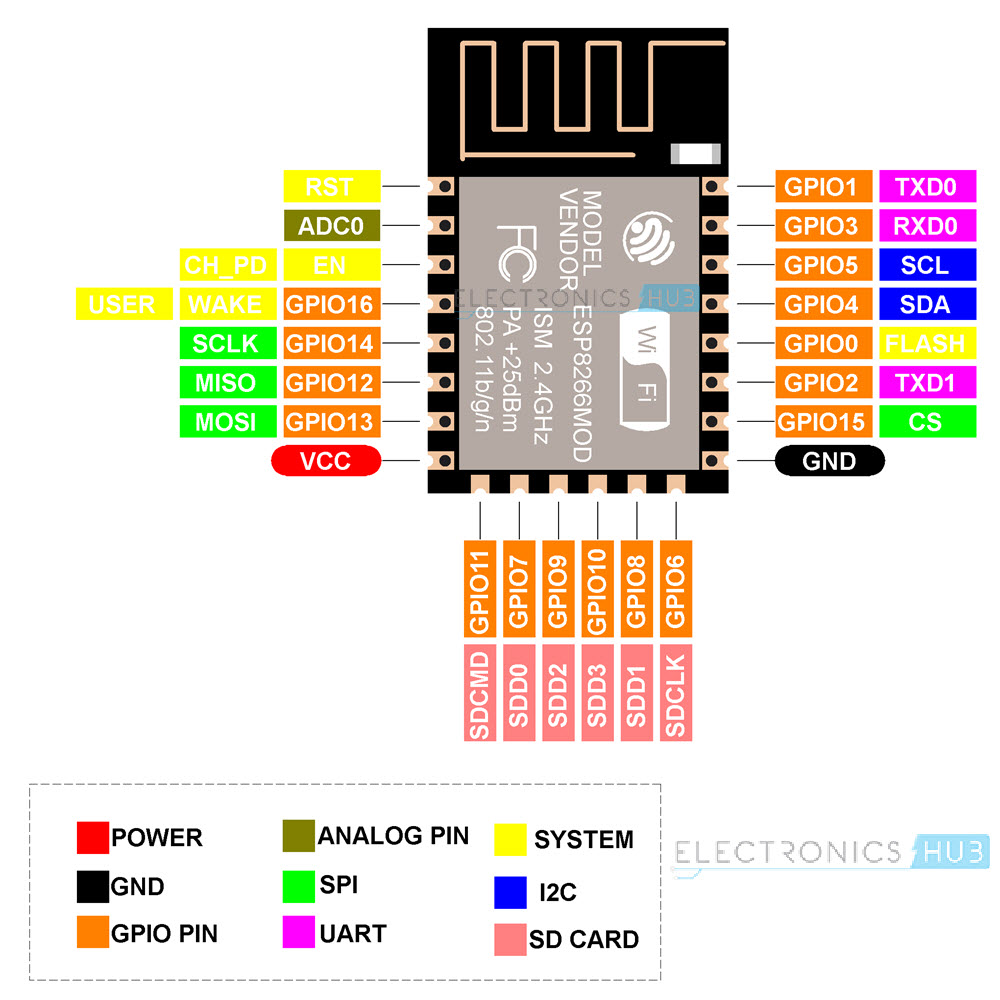
Here is the pin description of all the ESP-12E Pins.
| Pin | Function |
| RST | Reset the Module |
| ADC0 | ADC Pin with 10-bit resolution |
| EN | Chip Enable Pin (active HIGH) |
| GPIO16 | GPIO16 pin (wake pin from deep sleep mode) |
| GPIO14 | GPIO14 pin (HSPI_CLK) |
| GPIO12 | GPIO12 pin (HSPI_MISO) |
| GPIO13 | GPIO13 pin (HSPI_MOSI) |
| VCC | 3.3V Power Supply (max 3.6V) |
| SDCMD | SDIO CMD (GPIO11) |
| SDD0 | SDIO Data 0 (GPIO7) |
| SDD2 | SDIO Data 2 (GPIO9) |
| SDD3 | SDIO Data 3 (GPIO10) |
| SDD1 | SDIO Data 1 (GPIO8) |
| SCCLK | SDIO CLK (GPIO6) |
| GND | Ground Pin |
| GPIO15 | GPIO15 pin (HSPI_CS) |
| GPIO2 | GPIO2 pin (TXD1) |
| Flash | Flash Pin (GPIO0) |
| GPIO4 | GPIO4 pin (SDA – software I2C) |
| GPIO5 | GPIO5 pin (SCL – software I2C) |
| RXD0 | UART0 RXD pin (GPIO3) |
| TXD0 | UART0 TXD (GPIO1) |
Conclusion
Even though ESP32 is a more powerful and capable SoC, the ESP8266 is still one of the popular choices for Wi-Fi Chips. Several DIY, as well as professional products, integrate ESP8266 in one form or the other. That is either directly as an SoC or as a Module.
Regardless, if you want to design projects using ESP8266, then you have to be familiar with the pins and pin functions. In this guide, we saw the ESP8266 Pinout. First, we saw the pinout of the main ESP8266 SoC.
Then we saw the pinouts of some popular modules such as ESP-01 and ESP-12E. We also looked at the pinout of NodeMCU.
Link:https://www.electronicshub.org/esp8266-pinout/