The ESP8266 community created an add-on for the Arduino IDE that allows you to program the ESP8266 using the Arduino IDE and its programming language.
This tutorial shows how to install the ESP8266 board in Arduino IDE whether you’re using Windows, Mac OS X or Linux.
Watch the Video Tutorial
This tutorial is available in video format (watch below) and in written format (continue reading this page).
If you like the ESP8266 and want to build more projects, you can get my eBook: Home Automation using ESP8266.
Prerequisites: Arduino IDE Installed
Before starting this installation procedure, make sure you have the latest version of the Arduino IDE installed in your computer. If you don’t, uninstall it and install it again. Otherwise, it may not work.
Having the latest Arduino IDE software installed from arduino.cc/en/Main/Software, continue with this tutorial.
Do you need an ESP8266 board? You can buy it here.
Install ESP8266 Add-on in Arduino IDE
To install the ESP8266 board in your Arduino IDE, follow these next instructions:
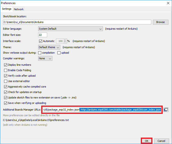
- In your Arduino IDE, go to File> Preferences

- Enter http://arduino.esp8266.com/stable/package_esp8266com_index.json into the “Additional Boards Manager URLs” field as shown in the figure below. Then, click the “OK” button:
 Note: if you already have the ESP32 boards URL, you can separate the URLs with a comma as follows:https://dl.espressif.com/dl/package_esp32_index.json, http://arduino.esp8266.com/stable/package_esp8266com_index.json
 - Open the Boards Manager. Go to Tools > Board > Boards Manager…

- Search for ESP8266 and press install button for the “ESP8266 by ESP8266 Community“:

- That’s it. It should be installed after a few seconds.

Testing the Installation
To test the ESP8266 add-on installation, let’s see if we can blink an LED with the ESP8266 using the Arduino programming language.
Here’s the hardware that you need to complete this project:
If you’re using an ESP8266-01, you also need an FTDI programmer to upload code.
You can use the preceding links or go directly to MakerAdvisor.com/tools to find all the parts for your projects at the best price!
Uploading the Sketch
Uploading the Sketch to the ESP-12E
If you’re using an ESP-12E NodeMCU Kit, uploading the sketch is very simple, since it has built-in programmer. Plug your board to your computer. Make sure you have the right board selected:

You also need to select the Port:

Then, copy the code provided:
/*********
  Rui Santos
  Complete project details at https://randomnerdtutorials.com
*********/

int pin = 2;

void setup() {
  // initialize GPIO 2 as an output.
  pinMode(pin, OUTPUT);
}

// the loop function runs over and over again forever
void loop() {
  digitalWrite(pin, HIGH);   // turn the LED on (HIGH is the voltage level)
  delay(1000);               // wait for a second
  digitalWrite(pin, LOW);    // turn the LED off by making the voltage LOW
  delay(1000);               // wait for a second
}
Click the “Upload” button in the Arduino IDE and wait a few seconds until you see the message “Done uploading.” in the bottom left corner.

Uploading the Sketch to the ESP-01
Uploading code to the ESP-01 requires establishing a serial communication between your ESP8266 and a FTDI Programmer as shown in the schematic diagram below.

ESP8266
FTDI programmer
RX
TX
TX
RX
CH_PD
3.3V
GPIO 0
GND
VCC
3.3V
GND
GND
If you have a brand new FTDI Programmer and you need to install your FTDI drivers on Windows PC, visit this website for the official drivers: http://www.ftdichip.com/Drivers/VCP.htm.
Then, you just need to connect the FTDI programmer to your computer, and upload the sketch to your ESP8266 board. You should see the “Done Uploading” message after a few seconds.
Schematic
If you’re using an ESP8266-12E
Connect an LED to your ESP8266, as shown in the following schematic diagram. The LED should be connected to GPIO 2 (D4).

link:https://randomnerdtutorials.com/how-to-install-esp8266-board-arduino-ide/