ESP32 is a low cost microcontroller device with wifi and bluetooth module integrated into the package. This chip was originally made by TSCM and fabricated using 40 nm transistors. It has various use case, one is to create a simple door lock with magnetic sensors.
But today, we are not going to built that complex system. Today, we are going to understand the basics of ESP32 by turning on and off an internal LED light and external LED light.
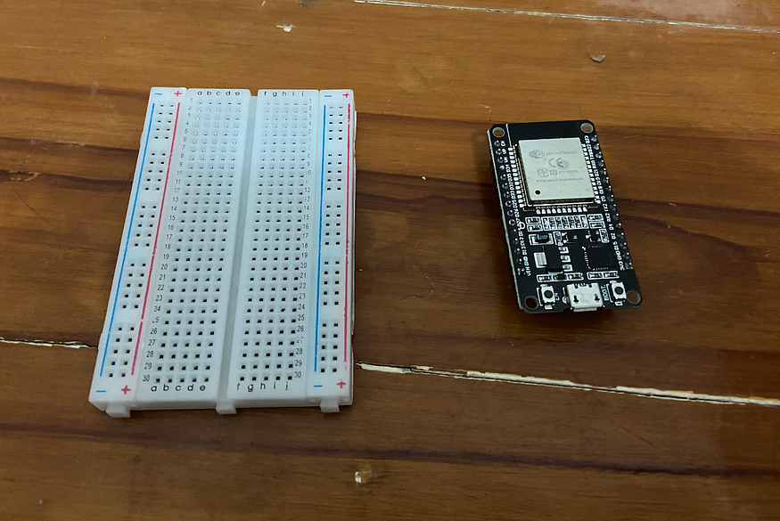
Components
What we need to create this simple project is
– 1 ESP32
– USB cable
– 5 Jumper Cable (Male to Male)
– 1 Breadboard
– 1Resister ( 330 Ohm)
– 1 LED Light (Any Color)
We also need to have an IDE named Arduino IDE and a basic understanding of any programming language to understand what the code really do. But, if you do not know how, you may also tag along as we will explain it in detail.
To watch how to install Arduino IDE, you may watch videos on youtube or read this simple how to do made by my lecture.
To understand ESP32 pins, you may also check the data sheet
Manipulate Your First LED Lights
Before we jump into the codes, we need to built the hardware first. First, connect your ESP32 to your breadboard
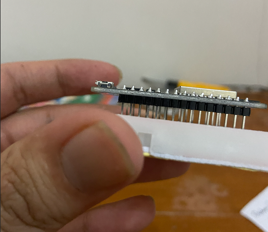
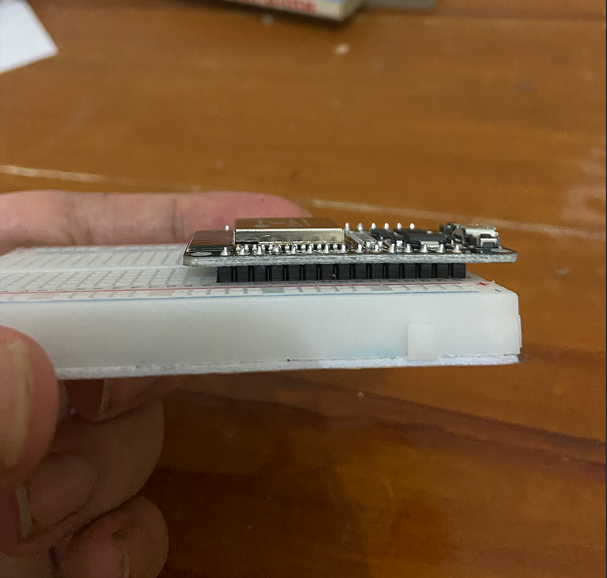
Once you installed the ESP32 to the breadboard, open your Arduino IDE and let’s start coding!
Programming the system
In the beginning, ESP32 does not know what it will do. To make it simple, it’s plain stupid and ready to be instructed by YOU.
First, create a new project, and then copy paste this code below :
#define LED1 2

void setup() {
  pinMode(LED1,OUTPUT);
}

void loop() {
  delay(1000);
  digitalWrite(LED1,HIGH);
  delay(1000);
  digitalWrite(LED1,LOW);
}
Now that you are done uploading it into the ESP32, you can see that the light is blinking and that’s how you know your code works and uploaded.

Upgrading The Project
Like what i have previously mentioned, this session will also cover turning on an external LED Light.
All you have to do is follow the previous steps with some tweaking. In this project, the breadboard will be a very crucial item as we will add LED into it.
Just like the previous lesson, we’ll start by setting up the hardware.
Adding LED into Breadboard
To add an external LED Light to your project, you need to have 1 LED Light, 2 Jumper cable, and an 220 Ohm Resistor.
Here are the steps to follow :
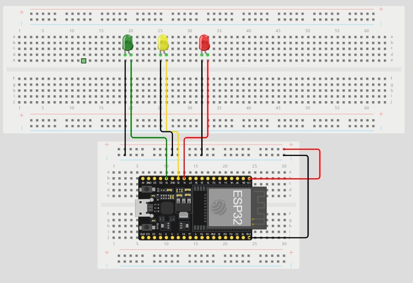
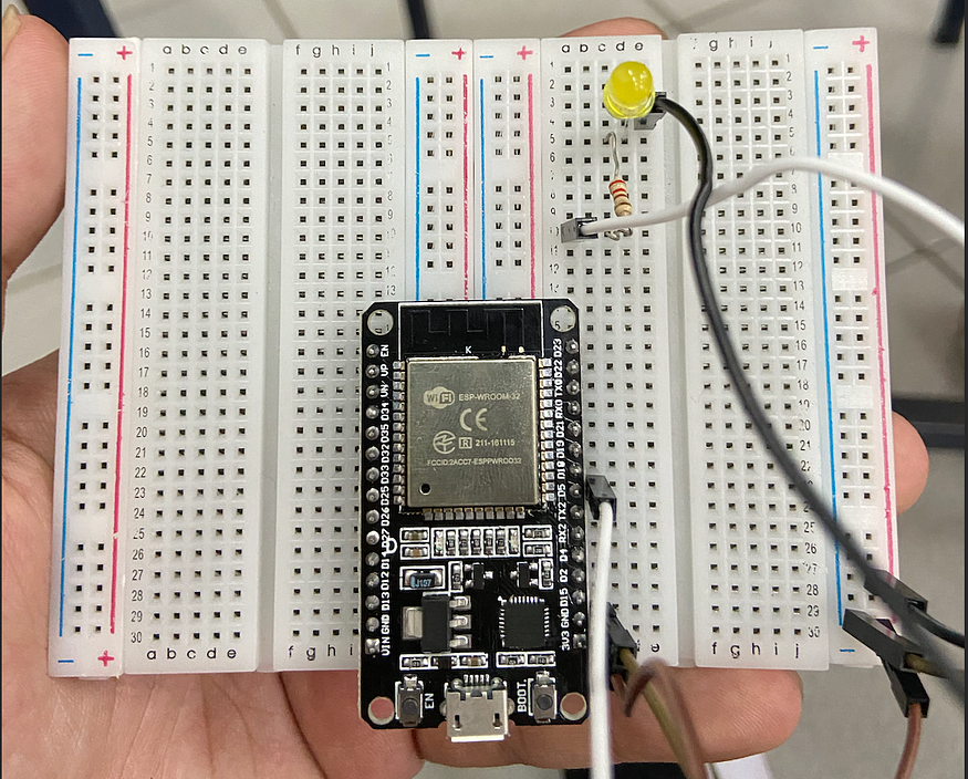
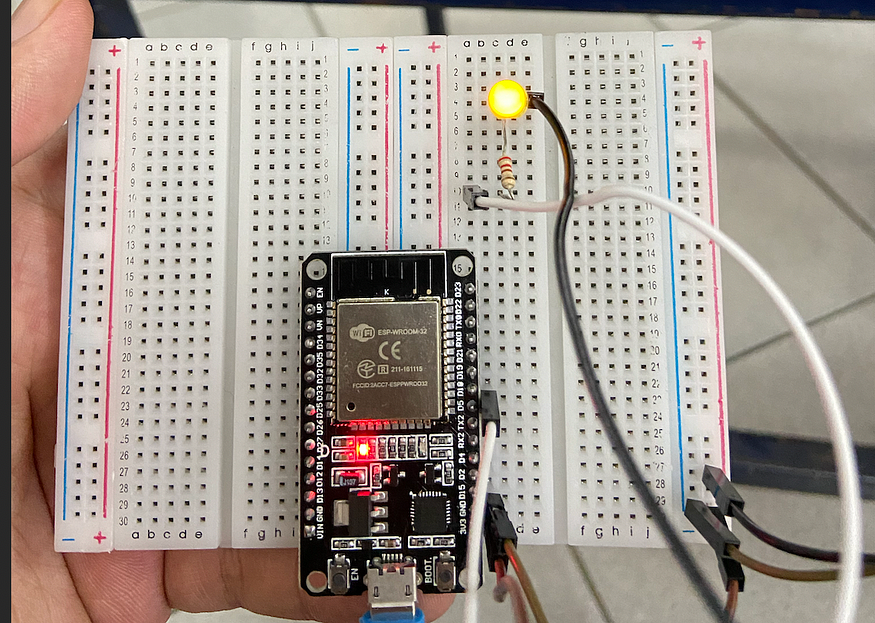
1. Connect your GND(Ground) pin to the negative part on your breadboard
2. Connect your 3V3 pin to the positive part on your breadboard
3. Connect your D5 pin to a resistor
4. Connect your resistor to an LED Light
5. Connect your LED Light to the positive side by using a jumper
The image above shows how it should have been done. If you have read the ESP32 data sheet, you should know that we’re playing with pin number 5 for the output.
Code The Program
All you have to do is copy paste this code to your arduino IDE
#define PIN5 5
void setup() {
  pinMode(PIN5,OUTPUT);
}
void loop() {
  delay(1000);
  digitalWrite(PIN5,HIGH);
  delay(1000);
  digitalWrite(PIN5,LOW);
}
I will not explain it deeply as it’s similar to the one on the previous project. The difference is we’re playing with pin number 5 while the previous project plays with pin number 2.
Finnish it
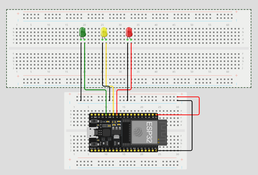
once you’re done with the code, upload it and you’ll see something simmilar to the image below
// === Ruthie Williams ====
// Module #3 project
const int red_LED1 = 14; // The red LED1 is wired to ESP32 board pin GPIO14
const int yellow_LED1 = 12; // The yellow LED1 is wired to ESP32 board pin GPIO12
const int green_LED1 = 13; // The green LED1 is wired to ESP32 board pin GPIO13
// the setup function runs once when you press reset or power the board
void setup()
{
pinMode(red_LED1, OUTPUT); // initialize digital pin GPIO14 (Red LED1) as an output.
pinMode(yellow_LED1, OUTPUT); // initialize digital pin GPIO12 (yellow LED1) as an
output.
pinMode(green_LED1, OUTPUT); // initialize digital pin GPIO13 (green LED1) as an
output.
}
// the loop function runs over and over again forever
void loop() {
// The next three lines of code turn on the red LED1
digitalWrite(red_LED1, HIGH); // This should turn on the RED LED1
digitalWrite(yellow_LED1 , LOW); // This should turn off the YELLOW LED1
digitalWrite(green_LED1, LOW); // This should turn off the GREEN LED1
delay(2000); // wait for 2 seconds
// The next three lines of code turn on the green LED1
digitalWrite(red_LED1, LOW); // This should turn off the RED LED1
digitalWrite(yellow_LED1 , LOW); // This should turn off the YELLOW LED1
digitalWrite(green_LED1, HIGH); // This should turn on the GREEN LED1
delay(2000); // wait for 2 seconds
// The next three lines of code turn on the yellow LED1
digitalWrite(red_LED1, LOW); // This should turn off the RED LED1
digitalWrite(yellow_LED1 , HIGH); // This should turn on the YELLOW LED1
digitalWrite(green_LED1, LOW); // This should turn off the GREEN LED1
delay(2000); // wait for 2 seconds
}
Link:https://medium.com/@fdika24/esp32-101-turning-on-led-lights-e4e7dc85d77 , https://wokwi.com/projects/392480522633384961