Today we’ll see a few ways of interfacing servo motors to the ESP32 microcontroller and controlling them with code, with a potentiometer, and over WiFi.
Introduction
We have already looked at both the ESP32 microcontroller and at using analog servo motors, and today we’ll put both of them together. We’ll see how to interface and control servo motors with the ESP32 and we’ll take advantage of the microcontrollers’ WiFi capabilities to control a servo with a web-based interface.
As you’ll soon see, controlling a servo motor with the ESP32 is quite similar to using an Arduino, with the added advantage of the ESP32’s wealth of ports and capabilities.
Servos & ESP32
#include <ESP32Servo.h>
Servo myservo;
void setup()
{
  myservo.attach(18);
}
void loop()
{
  myservo.write(0);
  delay(1000);
  myservo.write(90);
  delay(1000);
  myservo.write(180);
  delay(2000);
}
Controlling an analog servo motor, which is the type of servo motors most commonly used by hobbyists, is a task that most microcontrollers have no problem performing. Arduino’s, for example, have no problem controlling servos and the Arduino IDE even comes with a built-in servo motor library and a few bits of sample code to get you started.

So why use an ESP32, especially as most Arduino’s are less expensive? Depending upon your application there may be no reason, or there may be several. Here are a few:
- The ESP32 has a wealth of I/O ports, more than most Arduino’s.
- The ESP32 has analog outputs as well as analog inputs.
- There are built-in sensors in the ESP32, including a hall-effect sensor.
- The ESP32 has I/O pins that can be used as touch switches
- It has a lot of PWM output pins, so it can drive several servo motors.
- It has built-in WiFi and Bluetooth capabilities.
The latter reason is why many people choose the ESP32 over an Arduino for controlling servo motors. Built-in WiFi and Bluetooth open the door to all sorts of remote control possibilities.
Servo Motors
Servo motors are geared DC motors that have an integrated servomechanism with a feedback loop to allow precise positioning of the motor shaft. A high gear ratio allows a small servo to have an impressive torque rating.
Most servos are limited in rotation to either 180 or 270 degrees, with 180-degree servo motors being more common. There are specially modified servo motors that can rotate beyond 360-degrees, but we won’t be working with those today.
Servo motors come in a wide range of sizes and can be controlled either with an analog PWM signal or with a digital I/O signal. The inexpensive servos we use for hobbyist applications are usually analog servo motors, which are the types we will be using today.

A very common and inexpensive servo motor is the SG90. It’s a small plastic-gear servo that has become a standard for experimenting and is also used in a lot of RC hobby applications. It has a “cousin”, the MG90, which has similar specifications but uses metal gears.
The SG90, like most servo motors, can be powered from 5-6 volts, so servo motors are great for battery-powered applications.
Servo Motor Connections
Most analog servo motors like the SG90 use a 3-wire color-coded cable for interfacing. Although the color-coding is not an official standard many manufacturers use the same colored wires:
- Orange – The PWM servo control input. This is a logic-level signal, and most servo motors can accept 3.3-volt logic as well as 5-volt logic. Some models, especially 270-degree rotation servos, use a White wire for this connection.
- Red – The servo motor power supply input. Generally 5-6 volts DC, but be sure to check first.
- Brown – The ground connection. On some servo motors, this is a Black wire.

Most servo motor cables terminate in a 3-pin Dupont female connector. You can use jumper wires to connect this to a solderless breadboard.
Servo Positioning
Analog servo motors use PWM, or Pulse Width Modulation, to control the motor shaft position.
The PWM signal is usually about 50Hz, which is a period of 20ms. Within that period the pulse width is varied, a shorter pulse positions the servo towards the zero-degree mark while a longer one moves the motor shaft towards the 180 (or 270) degree position.
The pulse is continually applied to the control lead on the motor, locking the shaft into the desired position.
If you’d like a more detailed overview of servo motor operation check out the article Using Servo Motors with the Arduino.
ESP32 PWM
Most microcontrollers can be used to generate PWM signals and the ESP32 is certainly no exception. In fact, the ESP32 has the capability of controlling 16 PWM outputs independently.
One thing to note about the ESP32, however, is that many of the GPIO pins have multiple functions. So when selecting a PWM pin to use with your servo motor you’ll want to be sure that you don’t need one of the pins other functions in your design.
Even with that slight restriction, there are still several PWM pins available to drive servo motors, LEDs, and many other devices.
ESP32Servo Library
The Arduino IDE comes with a built-in servo motor control library, which is appropriately named “Servo”. Unfortunately, it won’t work with the ESP32.
There are many servo motor control libraries available for the ESP32, many of which emulate the Arduino Servo library while adding new functionality.
I’ve chosen to use the ESP32Servo Library by Kevin Harrington. This library duplicates the functionality of the original Arduino Servo library while adding a few extra features of its own.
IDE Setup
In order to work with ESP32 boards in the Arduino IDE, you are going to need to add a new Board Manager into the IDE. You’ll then use that new Board Manager to import the ESP32 boards and software examples.
You’ll need to open the Preferences box, which you’ll find under the File menu item, and then add the following location to the “Additional Boards Manager URLs” box:
After doing that and restarting the IDE you can go into the Boards Manager, which you’ll find under the Tools/Boards menu item, and search for ESP32. You should see an entry for “esp32 by Espressif Systems”. Highlight this entry and click on the Install button.
For more detailed instructions see my ESP32 introductory article.
Library Installation
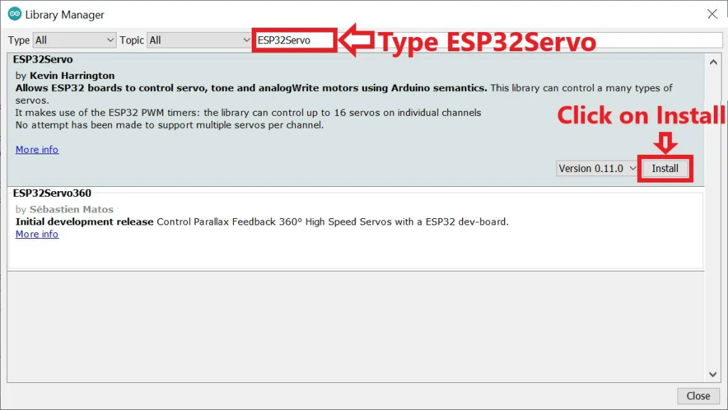
You can install the ESP32Servo Library directly from within your Arduino IDE using the Library Manager.
Open the Library Manager, which you’ll find under the Sketch/Include Library/Manage Libraries menu item.
Type “ESP32Servo” into the search box. From the displayed libraries select the ESP32Servo library, when you do the OK button will appear. Click that button to install the library.
Once the library is installed open your File/Examples menu and scroll down to the section for ESP32Servo. You’ll see a number of examples, some with familiar names. The ones that look familiar are modified versions of the example sketches from the Arduino Servo Library.
We are going to test out a couple of those sketches right now, but before we do we’ll need to get our ESP32 and servo motor all hooked up.
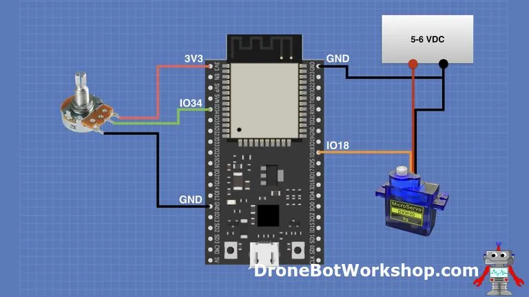
ESP32 Servo Hookup
For our first two experiments you’ll need the following parts:
- An ESP32 WROOM based module. You don’t need to use the same module I used, just make sure you have a pinout diagram of your module handy so that you can wire to the correct pins.
- A Servo Motor. I used an SG90, but any small analog servo motor will work. You can fine-tune the servo position in the code for just about any servo motor.
- A Potentiometer. I used a 10k linear pot, but any value from 5k upwards should work. Just make sure it is a linear-taper pot, i.e. it is at half-value when the shaft is turned to the halfway point.
- A Servo Power Supply. I always advocate powering motors with a power supply independent of the microcontroller. The servos usually need 5-6 volts. A 4-cell AA or AAA battery pack makes a great power supply for a servo motor.
For our experiments, you can just power the ESP32 using the USB connection to your computer. To run the circuit away from the computer you can use it’s 5-volt or 3.3-volt power pins to power it independently.
Here is the hookup, if your module has a different pinout then just make sure to use GPIO pin 18 for the PWM output. If you would like to use a different PWM-capable pin you’ll need to change the code to match.

For my tests, I elected to use a breadboard power supply to supply the motor voltage with 5-volts. You can also use a 6-volt battery or other suitable supply to power the motor.
Make sure you use 3.3-volts on the connection to the potentiometer and not 5-volts.

Once you have it all wired up connect it to your computer with the USB cable.
Example 1 – Sweep
The two examples we are going to look at are both updated versions of classic Arduino sketches. You won’t need to write any code, as these example sketches were included when you installed the ESP32Servo library.
/* Sweep
 by BARRAGAN <http://barraganstudio.com>
 This example code is in the public domain.

 modified 8 Nov 2013
 by Scott Fitzgerald

 modified for the ESP32 on March 2017
 by John Bennett

 see http://www.arduino.cc/en/Tutorial/Sweep for a description of the original code

 * Different servos require different pulse widths to vary servo angle, but the range is
 * an approximately 500-2500 microsecond pulse every 20ms (50Hz). In general, hobbyist servos
 * sweep 180 degrees, so the lowest number in the published range for a particular servo
 * represents an angle of 0 degrees, the middle of the range represents 90 degrees, and the top
 * of the range represents 180 degrees. So for example, if the range is 1000us to 2000us,
 * 1000us would equal an angle of 0, 1500us would equal 90 degrees, and 2000us would equal 1800
 * degrees.
 *
 * Circuit: (using an ESP32 Thing from Sparkfun)
 * Servo motors have three wires: power, ground, and signal. The power wire is typically red,
 * the ground wire is typically black or brown, and the signal wire is typically yellow,
 * orange or white. Since the ESP32 can supply limited current at only 3.3V, and servos draw
 * considerable power, we will connect servo power to the VBat pin of the ESP32 (located
 * near the USB connector). THIS IS ONLY APPROPRIATE FOR SMALL SERVOS.
 *
 * We could also connect servo power to a separate external
 * power source (as long as we connect all of the grounds (ESP32, servo, and external power).
 * In this example, we just connect ESP32 ground to servo ground. The servo signal pins
 * connect to any available GPIO pins on the ESP32 (in this example, we use pin 18.
 *
 * In this example, we assume a Tower Pro MG995 large servo connected to an external power source.
 * The published min and max for this servo is 1000 and 2000, respectively, so the defaults are fine.
 * These values actually drive the servos a little past 0 and 180, so
 * if you are particular, adjust the min and max values to match your needs.
 */

#include <ESP32Servo.h>

Servo myservo;  // create servo object to control a servo
// 16 servo objects can be created on the ESP32

int pos = 0;    // variable to store the servo position
// Recommended PWM GPIO pins on the ESP32 include 2,4,12-19,21-23,25-27,32-33
int servoPin = 13;

void setup() {
	// Allow allocation of all timers
	ESP32PWM::allocateTimer(0);
	ESP32PWM::allocateTimer(1);
	ESP32PWM::allocateTimer(2);
	ESP32PWM::allocateTimer(3);
	myservo.setPeriodHertz(50);    // standard 50 hz servo
	myservo.attach(servoPin, 500, 2400); // attaches the servo on pin 18 to the servo object
	// using default min/max of 1000us and 2000us
	// different servos may require different min/max settings
	// for an accurate 0 to 180 sweep
}

void loop() {

	for (pos = 0; pos <= 180; pos += 1) { // goes from 0 degrees to 180 degrees
		// in steps of 1 degree
		myservo.write(pos);    // tell servo to go to position in variable 'pos'
		delay(15);             // waits 15ms for the servo to reach the position
	}
	for (pos = 180; pos >= 0; pos -= 1) { // goes from 180 degrees to 0 degrees
		myservo.write(pos);    // tell servo to go to position in variable 'pos'
		delay(15);             // waits 15ms for the servo to reach the position
	}
}
The function of the Sweep sketch is pretty simple, it sweeps the servo motor shaft from zero to 180 degrees and then back to zero. It repeats this as long as it is powered up.
The only modifications made to the Sweep sketch from the original are the changes necessary to use the ESP32Servo library instead of the Arduino Servo library.
After including the ESP32Servo library we define an object called “myservo” to represent the servo motor. We also define the GPIO pin that the control input for the servo is connected to.
In the setup you will note the timer allocation statements, something you will need to do when using the ESP32Servo library.
We then define the frequency that we will be using to drive the servo control. 50Hz is pretty standard, but you can play with this value to improve servo performance.
Then we attach our servo object to the servo motor. You’ll notice three parameters here:
- The servo GPIO pin number.
- The minimum pulse width, which should drive the servo to the zero position.
- The maximum pulse width, which should drive the servo to its maximum position, typically 180 degrees.
The loop is very simple and consists of two for-loop counters. One counts from 0 to 180 and steps the servo in one direction, the other steps it in reverse back to the zero point. We then repeat everything.
Hook everything up, load up the code and take a look at it working. You should see the servo sweep back and forth.

When I did this it worked, but not very well. My servo motor did indeed sweep, but it wasn’t a full 180-degrees. More like about half that.
The way to fix this is to modify the sketch and change the values for the minimum and maximum time. Every servo is different so you can experiment to find the best fit for your motor. For the SG90 I was using the values of 500 and 2400 seemed to work.
Example 2 – Knob
Knob is another “classic” Arduino sketch, it’s entire purpose is to allow you to position a servo motor using a potentiometer. If that was ALL you wanted to do then using a microcontroller is a bit of an overkill, but of course, this is just a demonstration!
As with the Sweep sketch Knob has been modified to support the ESP32Servo library instead of the original Arduino library. It has also been adjusted to account for the increased resolution of the ESP32’s analog to digital converters (ADC) over the Arduino’s.
/*
 Controlling a servo position using a potentiometer (variable resistor)
 by Michal Rinott <http://people.interaction-ivrea.it/m.rinott>

 modified on 8 Nov 2013
 by Scott Fitzgerald

 modified for the ESP32 on March 2017
 by John Bennett

 see  http://www.arduino.cc/en/Tutorial/Knob for a description of the original code

 * Different servos require different pulse widths to vary servo angle, but the range is
 * an approximately 500-2500 microsecond pulse every 20ms (50Hz). In general, hobbyist servos
 * sweep 180 degrees, so the lowest number in the published range for a particular servo
 * represents an angle of 0 degrees, the middle of the range represents 90 degrees, and the top
 * of the range represents 180 degrees. So for example, if the range is 1000us to 2000us,
 * 1000us would equal an angle of 0, 1500us would equal 90 degrees, and 2000us would equal 1800
 * degrees.
 *
 * Circuit: (using an ESP32 Thing from Sparkfun)
 * Servo motors have three wires: power, ground, and signal. The power wire is typically red,
 * the ground wire is typically black or brown, and the signal wire is typically yellow,
 * orange or white. Since the ESP32 can supply limited current at only 3.3V, and servos draw
 * considerable power, we will connect servo power to the VBat pin of the ESP32 (located
 * near the USB connector). THIS IS ONLY APPROPRIATE FOR SMALL SERVOS.
 *
 * We could also connect servo power to a separate external
 * power source (as long as we connect all of the grounds (ESP32, servo, and external power).
 * In this example, we just connect ESP32 ground to servo ground. The servo signal pins
 * connect to any available GPIO pins on the ESP32 (in this example, we use pin 18.
 *
 * In this example, we assume a Tower Pro SG90 small servo connected to VBat.
 * The published min and max for this servo are 500 and 2400, respectively.
 * These values actually drive the servos a little past 0 and 180, so
 * if you are particular, adjust the min and max values to match your needs.
 */

// Include the ESP32 Arduino Servo Library instead of the original Arduino Servo Library
#include <ESP32Servo.h>

Servo myservo;  // create servo object to control a servo

// Possible PWM GPIO pins on the ESP32: 0(used by on-board button),2,4,5(used by on-board LED),12-19,21-23,25-27,32-33
int servoPin = 18;      // GPIO pin used to connect the servo control (digital out)
// Possible ADC pins on the ESP32: 0,2,4,12-15,32-39; 34-39 are recommended for analog input
int potPin = 34;        // GPIO pin used to connect the potentiometer (analog in)
int ADC_Max = 4096;     // This is the default ADC max value on the ESP32 (12 bit ADC width);
                        // this width can be set (in low-level oode) from 9-12 bits, for a
                        // a range of max values of 512-4096

int val;    // variable to read the value from the analog pin

void setup()
{
	// Allow allocation of all timers
	ESP32PWM::allocateTimer(0);
	ESP32PWM::allocateTimer(1);
	ESP32PWM::allocateTimer(2);
	ESP32PWM::allocateTimer(3);
  myservo.setPeriodHertz(50);// Standard 50hz servo
  myservo.attach(servoPin, 500, 2400);   // attaches the servo on pin 18 to the servo object
                                         // using SG90 servo min/max of 500us and 2400us
                                         // for MG995 large servo, use 1000us and 2000us,
                                         // which are the defaults, so this line could be
                                         // "myservo.attach(servoPin);"
}

void loop() {
  val = analogRead(potPin);            // read the value of the potentiometer (value between 0 and 1023)
  val = map(val, 0, ADC_Max, 0, 180);     // scale it to use it with the servo (value between 0 and 180)
  myservo.write(val);                  // set the servo position according to the scaled value
  delay(200);                          // wait for the servo to get there
}
The servo motor object is created and attached exactly as it was in the previous sketch.
Note the value of 4096 for ADC_Max, it represents the maximum value for the analog to digital converter. By default, the ESP32 uses a 12-bit A/D converter.
In the loop, all we do is read the potentiometer position by obtaining a value from the A/D converter. This is mapped to a range of 0-180.
We then use this value to write to the servo object, which moves the servo motor to the desired position.

Run the sketch and twist the potentiometer. You should observe the servo motor moving when you move the potentiometer.
Multiple Servos with PCA9685
The ESP32 has the capability of driving 16 PWM channels, so you can drive several servo motors directly. Some ESP32 Servo libraries only support a limited number of motors, however, the ESP32Servo library that we are using will support all 16 PWM pins.
However, bear in mind that the GPIO pins that support PWM also have other functions, some of which you might need in your project.
You also might need MORE than 16 servo motors for a project as wild as it might sound. A “robot spider” with eight legs and three degrees of freedom per leg would need 24 servo motors, give it four degrees of freedom and the number goes up to 32.
Or you may want to minimize the number of connections to the ESP32, or locate your motors away (but not too far away) from the microcontroller.
All of these requirements sound like a good fit for the PCA9685.
PCA9685 16-Channel PWM Module
The PCA96845 is a 16-channel PWM controller module that can be used with servo motors, LEDs, and pretty well anything that you can control with a PWM pulse.
The module is an I2C device, so all of the work of timing and producing PWM signals is done onboard, freeing the host device (the ESP32 in this case) from having to deal with it.
This device has six selectable address bits, and you can cascade up to 62 of them on the same I2C bus. This would allow you to control up to 992 servo motors!

You can buy the device assembled or as a board with headers and terminals that you solder in yourself, allowing you more flexibility in incorporating the PCA9685 into your project.
The connections on the PCA9685 module are duplicated on each end, making it easy to use multiple modules. By using right-angled Dupont male and female connectors you could “daisy chain” the modules. Just make sure to select a unique I2C address for each module.
As I don’t have 992 servo motors in stock in the workshop at the moment I’ll confine myself to one module and two servo motors, but the coding principles can be extended to any number of modules and servo motors.
ESP32 PCA9685 Hookup
The PCA9685 is an I2C device and can operate with either 3.3 or 5-volt logic and power. We will be using 3.3-volt logic and will power the module from the ESP32.

The I2C connections to the ESP32 are as follows:
- SDA – IO21
- SCL – IO22
Actually you can use any two pins on the ESP32 for your I2C connections and define them in software. GPIO pins 21 and 22 are the default if new pins are not declared.
You’ll note the use of pullup resistors for the I2C data and clock lines. As we are using 3.3-volt logic you should use values in the 2.4k to 3.3k neighborhood.
I connected my servo motors to connectors 0 and 12, but you can choose any two you like, and you may add more servo motors. When you look at the code you’ll see how to define your motor hookup and how to address each motor.
For a power supply, I used a battery-holder with four type AA batteries. Any 5 or 6-volt power supply should suffice, especially if you are using small SG90 servo motors as I did.
ESP32 PCA9685 Code
A great source for obtaining PCA9685 modules is Adafruit, and if you know Adafruit then you’ll know that they don’t sell anything without creating extensive documentation, articles, code samples, and libraries. The PCA9685 is no different, so we will be using an Adafruit library that works with both the Arduino and the ESP32.
Here is the sketch I used to control the two servo motors using the ESP32 and the PCA9685.
/*
  ESP32 PCA9685 Servo Control
  esp32-pca9685.ino
  Driving multiple servo motors with ESP32 and PCA9685 PWM module
  Use I2C Bus

  DroneBot Workshop 2020
  https://dronebotworkshop.com
*/

// Include Wire Library for I2C
#include <Wire.h>

// Include Adafruit PCA9685 Servo Library
#include <Adafruit_PWMServoDriver.h>

// Creat object to represent PCA9685 at default I2C address
Adafruit_PWMServoDriver pca9685 = Adafruit_PWMServoDriver(0x40);

// Define maximum and minimum number of "ticks" for the servo motors
// Range from 0 to 4095
// This determines the pulse width

#define SERVOMIN  80  // Minimum value
#define SERVOMAX  600  // Maximum value

// Define servo motor connections (expand as required)
#define SER0  0   //Servo Motor 0 on connector 0
#define SER1  12  //Servo Motor 1 on connector 12

// Variables for Servo Motor positions (expand as required)
int pwm0;
int pwm1;

void setup() {

  // Serial monitor setup
  Serial.begin(115200);

  // Print to monitor
  Serial.println("PCA9685 Servo Test");

  // Initialize PCA9685
  pca9685.begin();

  // Set PWM Frequency to 50Hz
  pca9685.setPWMFreq(50);

}

void loop() {

  // Move Motor 0 from 0 to 180 degrees
  for (int posDegrees = 0; posDegrees <= 180; posDegrees++) {

    // Determine PWM pulse width
    pwm0 = map(posDegrees, 0, 180, SERVOMIN, SERVOMAX);
    // Write to PCA9685
    pca9685.setPWM(SER0, 0, pwm0);
    // Print to serial monitor
    Serial.print("Motor 0 = ");
    Serial.println(posDegrees);
    delay(30);
  }

  // Move Motor 1 from 180 to 0 degrees
  for (int posDegrees = 180; posDegrees >= 0; posDegrees--) {

    // Determine PWM pulse width
    pwm1 = map(posDegrees, 0, 180, SERVOMIN, SERVOMAX);
    // Write to PCA9685
    pca9685.setPWM(SER1, 0, pwm1);
    // Print to serial monitor
    Serial.print("Motor 1 = ");
    Serial.println(posDegrees);
    delay(30);
  }

  // Move Motor 0 from 180 to 0 degrees
  for (int posDegrees = 180; posDegrees >= 0; posDegrees--) {

    // Determine PWM pulse width
    pwm0 = map(posDegrees, 0, 180, SERVOMIN, SERVOMAX);
    // Write to PCA9685
    pca9685.setPWM(SER0, 0, pwm0);
    // Print to serial monitor
    Serial.print("Motor 0 = ");
    Serial.println(posDegrees);
    delay(30);
  }


  // Move Motor 1 from 0 to 180 degrees
  for (int posDegrees = 0; posDegrees <= 180; posDegrees++) {

    // Determine PWM pulse width
    pwm1 = map(posDegrees, 0, 180, SERVOMIN, SERVOMAX);
    // Write to PCA9685
    pca9685.setPWM(SER1, 0, pwm1);
    // Print to serial monitor
    Serial.print("Motor 1 = ");
    Serial.println(posDegrees);
    delay(30);
  }


}
The code makes use of an Adafruit library for the PCA9685, the Adafruit PWM Servo Driver library. You can obtain this directly within your Library Manager, just as you did with the ESP32Servo library.
We also use the Wire library, which is the built-in library for working with I2C.
As with our previous sketches we need to calculate some values to represent the minimum and maximum pulse width for our servo motors. Unlike the previous sketches we don’t specify this time period in microseconds but instead in “ticks”.
So what is a “tick”?
A tick is a time period used by the PCA9685. On the PCA9685 you specify a pulse frequency in Hz. Each cycle of the pulse is divided into 4096 periods called “ticks”.
To make the pulse have a 50% duty-cycle you would hold it HIGH for the first 2048 ticks and then low for the remaining 2048 ticks. For a 25% duty-cycle you would keep it HIGH for only 1024 ticks.
So the constants SERVOMIN and SERVOMAX represent the number of ticks in the minimum and maximum pulse widths.
Next, we define connections for our individual servo motors. As I connected my first motor on connector 0 and my second one on connector 12 I used 0 and 12, you can, of course, connect to any of the 16 connectors and define your motors accordingly.
I also defined a couple of variables to be used to represent the servo position.
In the Setup, we initialize the Serial Monitor, note the baud rate which is typical of ESP32 projects. We also print to the monitor.
Then we initialize the PCA9685 and set its PWM frequency to 50Hz. You can experiment with this to improve your servo performance if you wish.
In the Loop, I got lazy and essentially copied the Sweep example twice! The difference here is that I’m driving the two servo motors and alternating between them.
The key to understanding this part of the code is to see how the position data is written to the servo motor. The setPWM function from the Adafruit library is used to position the motor. It has three parameters:
- The Servo connector number, from 0 to 15
- The Starting Tick for the pulse. In this example it is always set to 0.
- The Ending Tick for the pulse.
The tick values are determined using a map command against the SERVOMIN and SERVOMAX values.

Hook everything up and load the code and then reset the ESP32. You should observe the two motors alternating through sweeps.
Web Remote Controlled Servo
Probably the greatest attraction of using an ESP32 with a servo motor is the potential for developing a remote control system using the ESP32s Bluetooth or WiFi.
Creating a remote control requires a two-way conversation between the users’ browser and the web server created by the ESP32. Traffic back from the browser can take several forms, from simple GET requests on the URL line to AJAX. The ESP32 returns HTTP traffic to the web browser.
Here is a very simple web-based control for a servo motor. It has one control, a slider, whose purpose is to control the position or angle of the servo shaft.
ESP32 Web Server Hookup
If you have the breadboard still set up from our first experiments you can use it as-is.

The only difference with the wiring is that we are no longer using the potentiometer, so you may remove it if you wish.
Make sure you know your WiFi SSID and password, as you’ll be needing it when coding. The ESP32 only supports 2.4GHz WiFi.
ESP32 Web Server Code
One of the best resources for ESP32 information on the web is the Random Nerd Tutorials website. These folks (Rui and Sara Santos) are so good that Espressif, the company that manufactures the ESP32, refers to them on their blog as a source of quality ESP32 information.
I’ve used their site many times in my own ESP32 research, the following sketch is a blatant copy of one that Rui Santos wrote for Random Nerd Tutorials. I’ve only modified it in two slightly significant ways:
- I changed the servo library to the ESP32Servo library, as Rui was using a different one.
- I styled the page a bit differently. Mine is blue!
The sketch is not only a great example of controlling a servo motor with a web-based interface, it’s a great example of controlling really anything with a web-based interface.
The sketch starts a web server and creates a webpage that has a slider control. Sliding the control to a different position causes that position to be sent back to the ESP32 using AJAX. The ESP32 then positions the servo motor accordingly.
You could use the same arrangement to send numerical data to control almost anything, and of course you could add more controls using the same technique.
Here is the sketch:
/*
ESP32 Remote WiFi Servo Control
esp32-web-servo.ino
Control servo motor from web page
Based upon example from Rui Santos
Random Nerd Tutorials
https://randomnerdtutorials.com/esp32-servo-motor-web-server-arduino-ide/
DroneBot Workshop 2020
Welcome to the Workshop!
*/
#include <WiFi.h>
#include <ESP32Servo.h>
Servo myservo; // create servo object to control a servo
// Servo GPIO pin
static const int servoPin = 18;
// Network credentials
const char* ssid = "YOURSSID";
const char* password = "YOURPW";
// Web server on port 80 (http)
WiFiServer server(80);
// Variable to store the HTTP request
String header;
// Decode HTTP GET value
String valueString = String(5);
int pos1 = 0;
int pos2 = 0;
// Current time
unsigned long currentTime = millis();
// Previous time
unsigned long previousTime = 0;
// Define timeout time in milliseconds (example: 2000ms = 2s)
const long timeoutTime = 2000;
void setup() {
// Allow allocation of all timers for servo library
ESP32PWM::allocateTimer(0);
ESP32PWM::allocateTimer(1);
ESP32PWM::allocateTimer(2);
ESP32PWM::allocateTimer(3);
// Set servo PWM frequency to 50Hz
myservo.setPeriodHertz(50);
// Attach to servo and define minimum and maximum positions
// Modify as required
myservo.attach(servoPin,500, 2400);
// Start serial
Serial.begin(115200);
// Connect to Wi-Fi network with SSID and password
Serial.print("Connecting to ");
Serial.println(ssid);
WiFi.begin(ssid, password);
while (WiFi.status() != WL_CONNECTED) {
delay(500);
Serial.print(".");
}
// Print local IP address and start web server
Serial.println("");
Serial.println("WiFi connected.");
Serial.println("IP address: ");
Serial.println(WiFi.localIP());
server.begin();
}
void loop(){
// Listen for incoming clients
WiFiClient client = server.available();
// Client Connected
if (client) {
// Set timer references
currentTime = millis();
previousTime = currentTime;
// Print to serial port
Serial.println("New Client.");
// String to hold data from client
String currentLine = "";
// Do while client is cponnected
while (client.connected() && currentTime - previousTime <= timeoutTime) {
currentTime = millis();
if (client.available()) { // if there's bytes to read from the client,
char c = client.read(); // read a byte, then
Serial.write(c); // print it out the serial monitor
header += c;
if (c == '\n') { // if the byte is a newline character
// if the current line is blank, you got two newline characters in a row.
// that's the end of the client HTTP request, so send a response:
if (currentLine.length() == 0) {
// HTTP headers always start with a response code (e.g. HTTP/1.1 200 OK) and a content-type
client.println("HTTP/1.1 200 OK");
client.println("Content-type:text/html");
client.println("Connection: close");
client.println();
// Display the HTML web page
// HTML Header
client.println("<!DOCTYPE html><html>");
client.println("<head><meta name=\"viewport\" content=\"width=device-width, initial-scale=1\">");
client.println("<link rel=\"icon\" href=\"data:,\">");
// CSS - Modify as desired
client.println("<style>body { text-align: center; font-family: \"Trebuchet MS\", Arial; margin-left:auto; margin-right:auto; }");
client.println(".slider { -webkit-appearance: none; width: 300px; height: 25px; border-radius: 10px; background: #ffffff; outline: none; opacity: 0.7;-webkit-transition: .2s; transition: opacity .2s;}");
client.println(".slider::-webkit-slider-thumb {-webkit-appearance: none; appearance: none; width: 35px; height: 35px; border-radius: 50%; background: #ff3410; cursor: pointer; }</style>");
// Get JQuery
client.println("<script src=\"https://ajax.googleapis.com/ajax/libs/jquery/3.3.1/jquery.min.js\"></script>");
// Page title
client.println("</head><body style=\"background-color:#70cfff;\"><h1 style=\"color:#ff3410;\">Servo Control</h1>");
// Position display
client.println("<h2 style=\"color:#ffffff;\">Position: <span id=\"servoPos\"></span>°</h2>");
// Slider control
client.println("<input type=\"range\" min=\"0\" max=\"180\" class=\"slider\" id=\"servoSlider\" onchange=\"servo(this.value)\" value=\""+valueString+"\"/>");
// Javascript
client.println("<script>var slider = document.getElementById(\"servoSlider\");");
client.println("var servoP = document.getElementById(\"servoPos\"); servoP.innerHTML = slider.value;");
client.println("slider.oninput = function() { slider.value = this.value; servoP.innerHTML = this.value; }");
client.println("$.ajaxSetup({timeout:1000}); function servo(pos) { ");
client.println("$.get(\"/?value=\" + pos + \"&\"); {Connection: close};}</script>");
// End page
client.println("</body></html>");
// GET data
if(header.indexOf("GET /?value=")>=0) {
pos1 = header.indexOf('=');
pos2 = header.indexOf('&');
// String with motor position
valueString = header.substring(pos1+1, pos2);
// Move servo into position
myservo.write(valueString.toInt());
// Print value to serial monitor
Serial.print("Val =");
Serial.println(valueString);
}
// The HTTP response ends with another blank line
client.println();
// Break out of the while loop
break;
} else {
// New lline is received, clear currentLine
currentLine = "";
}
} else if (c != '\r') { // if you got anything else but a carriage return character,
currentLine += c; // add it to the end of the currentLine
}
}
}
// Clear the header variable
header = "";
// Close the connection
client.stop();
Serial.println("Client disconnected.");
Serial.println("");
}
}The sketch makes use of the built-in WiFi Library for connectivity, as well as the ESP32Servo library.
You’ll need to supply your wifi credentials, remember that the ESP32 only works on 2.4GHz wifi.
In the Setup, we get the servo prepared and set the PWM frequency as well as the minimum and maximum points of travel, as we did before.
We then start the serial monitor, which will be needed to determine the IP address assigned to our ESP32 web server.
We connect to the wifi network using the supplied credentials and report the progress on the serial monitor. The assigned IP address is printed so that we can use a web browser to see our control.
In the loop, we listen for clients, which occur when someone loads or modifies our web page. When a client connection is detected we serve a web page and monitor for data sent back from the client.
The data being sent back will come from a slider control, which is being used to set the servo motor position. When the slider is moved its position value is sent back to the web server.
This value is embedded in GET data in two parts, which are combined and converted to an integer to position the servo using the servo library functions.
Once this is done we print the value to the serial monitor and then close the client connection. We then end the loop and start listening for another client connection.
ESP32 Web Server HTML
You can modify the sketch to style the website any way you want to, although for your first test I’d advise sticking with this code until you can at least verify that everything is working.
The HTML in the code is not that easy to read, as it is entered in the way the webserver will send it as opposed to a more human-readable fashion.
So here is the HTML portion of the code in a more conventional format.
<!DOCTYPE html>
<html>
<head>
<meta name="viewport" content="width=device-width, initial-scale=1">
<link rel="icon" href="data:,">
<style>
body {
text-align: center;
font-family: "Trebuchet MS", Arial;
margin-left:auto;
margin-right:auto;
}
.slider {
-webkit-appearance: none;
width: 300px;
height: 25px;
border-radius: 10px;
background: #ffffff;
outline: none;
opacity: 0.7;
-webkit-transition: .2s;
transition: opacity .2s;
}
.slider::-webkit-slider-thumb {
-webkit-appearance: none;
appearance: none;
width: 35px;
height: 35px;
border-radius: 50%;
background: #ff3410;
cursor: pointer;
}
</style>
<script src="https://ajax.googleapis.com/ajax/libs/jquery/3.3.1/jquery.min.js"></script>
</head>
<body style="background-color:#70cfff;">
<h1 style="color:#ff3410;">Servo Control</h1>
<h2 style="color:#ffffff;">Position: <span id="servoPos"></span>°</h2>
<input type="range" min="0" max="180" class="slider" id="servoSlider" onchange="servo(this.value)"/>
<script>
var slider = document.getElementById("servoSlider");
var servoP = document.getElementById("servoPos");
servoP.innerHTML = slider.value;
slider.oninput = function() {
slider.value = this.value;
servoP.innerHTML = this.value;
}
$.ajaxSetup({timeout:1000});
function servo(pos) {
$.get("/?value=" + pos + "&");
{Connection: close};
}
</script>
</body>
</html>You can save the above as an HTML file if you like and then open it in your browser. Experiment with the CSS style settings to see the effects.
Once you have it looking the way you want, make note of the changed values, and adjust the sketch accordingly.
ESP32 Web Server Testing
Testing and troubleshooting the web-based interface is best done with both a web browser and the Arduino IDE Serial Monitor.
You’ll need to use the IDE to begin. Start or reset the ESP32 and look at the boot message. You should see the ESP32 attempt to connect to your WiFi network using the credentials you supplied.

If the device fails to connect, reset it and try again, often the DHCP server in the router times out on the first try.
If it connects then you’ll see the IP address assigned to the ESP32 printed on the Serial Monitor. Make note of that address, as it’s the one you’ll need to point your web browser to.
If you still can’t connect go back and check the network name and password you supplied. Restarting your router may help if everything else fails.
Once you are connected you should see a screen with a slider. Above the slider is some test displaying the current servo position in degrees.
Move the slider and observe your servo motor, if all is working well it will move.

Watch the Serial Monitor when you move the slider. You will notice that for every move the client opens and closes a connection and passes a variable, which is displayed in the Serial Monitor. That variable should be the position of the slider. The variable is fed to the servo, moving it into position.
Experiment with the code, change the colors and see if you can add a second servo to the system.
Conclusion
The ESP32 offers a number of servo motor control possibilities. With its wealth of GPIO pins and the ability to drive a large number of servos, as well as the built-in WiFi and Bluetooth, it can certainly make a good fit for any servo motor control project.
And don’t overlook another advantage of the ESP32 – it’s performance. This is an advanced microcontroller that can run at speeds up to 20 times faster than an Arduino, and it’s a 32-bit dual-core device as well.
One advanced use for servos with an ESP32 would be object or face tracking. Two ESP32-driven servo motors could operate a pan-and-tilt platform with a camera that tracks objects or faces.
Knowing how to interface servo motors to an ESP32 is a skill that is sure to pay off. I can’t wait to see what you design!
LInk:https://dronebotworkshop.com/esp32-servo/ , https://www.electronicwings.com/esp32/servo-motor-interfacing-with-esp32