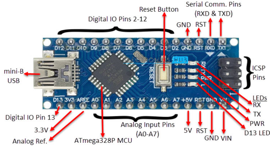
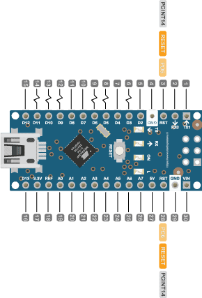
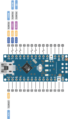
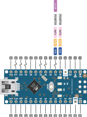
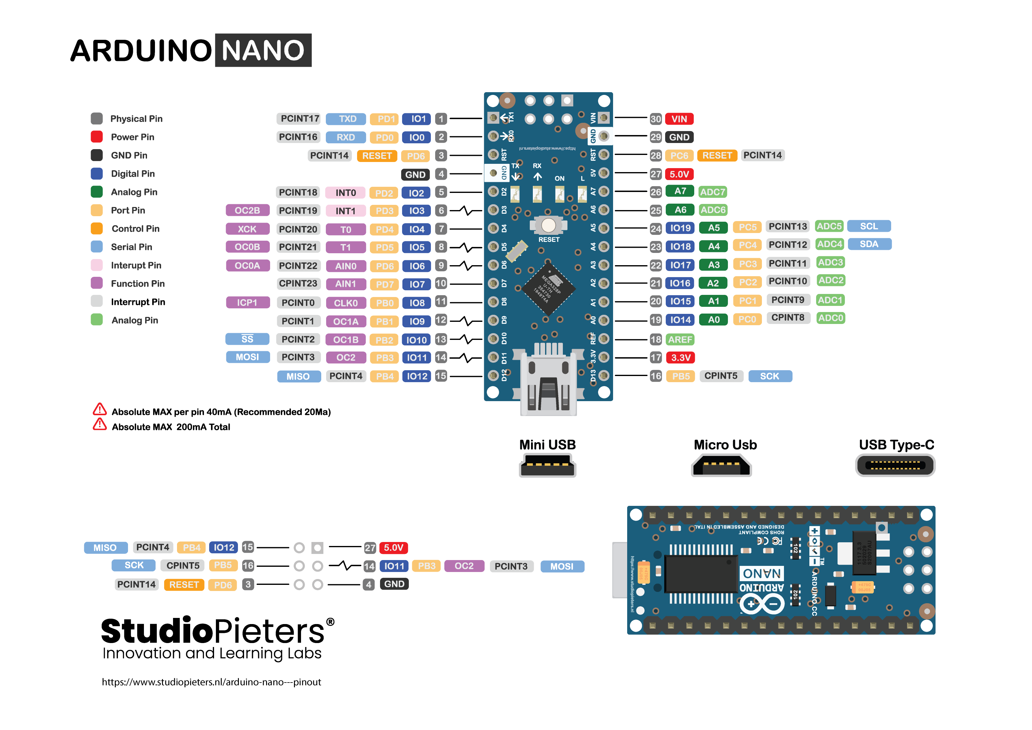
In this post, we’ll be taking a closer look at the Arduino® Nano hardware, and more specifically, the Arduino® Nano pinout. Arduino® Nano is based on the ATmega328 by Atmel. The Arduino® Nano pinout consists of 14 digital pins, 6 analogue inputs, USB connection and ICSP header. The versatility of the pinout provides many different options such as driving motors, LED’s, reading sensors and more. In this post, we’ll go over the capabilities of the Arduino® Nano pinout.

Power Supply
There are 2 ways to power the Arduino® Nano, the first is the VIN Pin. This pin is used to power the Arduino® Nano board using an external power source. The board can be powered by 5-20 volts, but the manufacturer recommends keeping it between 7-12 volts. Above 12 volts, the regulators might overheat, and below 7 volts, might not suffice. The Second one is the USB connector, when connected to the computer, provides 5 volts at 500mA.
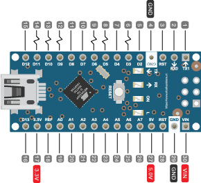
The power source you use determines the power you have available for your circuit. For instance, powering the circuit using the USB limits you to 500mA. Take into consideration that this is also used for powering the MCU, its peripherals, the on-board regulators, and the components connected to it. The 5.0V and 3.3V Pin provide regulated 5.0V and 3.3V to power external components according to manufacturer specifications. You can find 2 GND pins on the Arduino® Nano, which are all interconnected.
The GND pins are used to close the electrical circuit and provide a common logic reference level throughout your circuit. Always make sure that all GND’s (of the Arduino, peripherals and components) are connected to one another and have a common ground.
You can find 2 reset pin’s and one button on the Arduino® Nano, which are all interconnected.
Analog
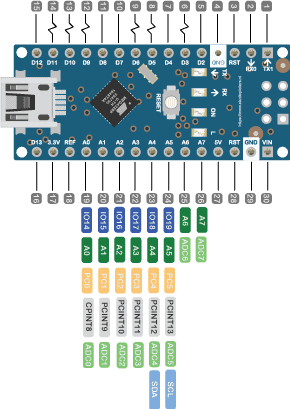
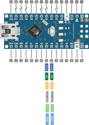
The Arduino® Nano has 8 analogue pins, which utilize ADC (Analogue to Digital converter). These pins serve as analogue inputs, but can also function as digital inputs or digital outputs.
Analog to Digital Conversion
ADC stands for Analogue to Digital Converter. ADC is an electronic circuit used to convert analogue signals into digital signals. This digital representation of analogue signals allows the processor (which is a digital device) to measure the analogue signal and use it through its operation. Arduino Pins A0-A7 are capable of reading analogue voltages. On Arduino, the ADC has 10-bit resolution, meaning it can represent analogue voltage by 1,024 digital levels. The ADC converts voltage into bits which the microprocessor can understand.
Digital Pins
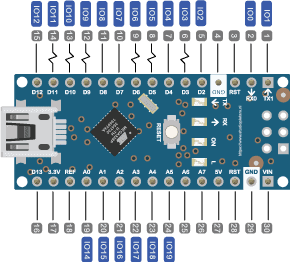
Pins 0-13 of the Arduino® Nano serve as digital input/output pins. Pin 13 of the Arduino® Nano is connected to the built-in LED. In the Arduino® Nano – pins 3,5,6,9,10,11 have PWM capability.
Note: Each pin can provide/sink up to 40 mA max. But the recommended current is 20 mA. The absolute max current provided (or sank) from all pins together is 200mA.
Digital
Digital is a way of representing voltage in 1 bit: either 0 or 1. Digital pins on the Arduino are pins designed to be configured as inputs or outputs according to the needs of the user. Digital pins are either on or off. When ON they are in a HIGH voltage state of 5V and when OFF they are in a LOW voltage state of 0V. On the Arduino® Nano, When the digital pins are configured as output, they are set to 0 or 5 volts.
When the digital pins are configured as input, the voltage is supplied from an external device. This voltage can vary between 0-5 volts, which is converted into digital representation (0 or 1). To determine this, there are 2 thresholds: Below 0.8v – considered as 0. Above 2v – considered as 1. When connecting a component to a digital pin, make sure that the logic levels match. If the voltage is in between the thresholds, the returning value will be undefined.
PWM
In general, Pulse Width Modulation (PWM) is a modulation technique used to encode a message into a pulsing signal. A PWM is composed of two key components: frequency and duty cycle. The PWM frequency dictates how long it takes to complete a single cycle (period) and how quickly the signal fluctuates from high to low. The duty cycle determines how long a signal stays high out of the total period. Duty cycle is represented in percentage.
In Arduino, the PWM enabled pins produce a constant frequency of ~ 500Hz, while the duty cycle changes according to the parameters set by the user. See the following illustration:
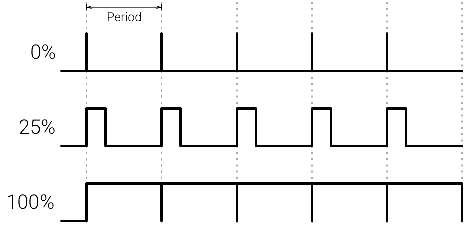
PWM signals are used for speed control of DC motors, dimming LEDs and more.
Serial Communication
Serial communication is used to exchange data between the Arduino board and another serial device such as computers, displays, sensors and more. Each Arduino board has at least one serial port. Serial communication occurs on digital pins 0 (RX) and 1 (TX) as well as via USB. Arduino supports serial communication through digital pins with the Software Serial Library as well. This allows the user to connect multiple serial-enabled devices and leave the main serial port available for the USB.
Software serial and hardware serial – Most microcontrollers have hardware designed to communicate with other serial devices. Software serial ports use a pin-change interrupt system to communicate. There is a built-in library for Software Serial communication. Software serial is used by the processor to simulate extra serial ports. The only drawback with software serial is that it requires more processing and cannot support the same high speeds as hardware serial.
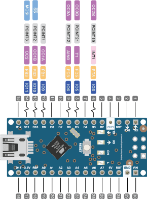
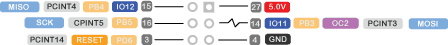
SPI – SS/SCK/MISO/MOSI pins are the dedicated pins for SPI communication. They can be found on digital pins 10-13 of the Arduino® Nano and on the ICSP headers.
SPI
Serial Peripheral Interface (SPI) is a serial data protocol used by microcontrollers to communicate with one or more external devices in a bus like connection. The SPI can also be used to connect 2 microcontrollers. On the SPI bus, there is always one device that is denoted as a Master device and all the rest as slaves. In most cases, the microcontroller is the Master device. The SS (Slave Select) pin determines which device the Master is currently communicating with. SS/SCK/MISO/MOSI pins are the dedicated pins for SPI communication. They can be found on digital pins 10-13 of the Arduino UNO and on the ICSP headers. SPI enabled devices always have the following pins:
MISO (Master In Slave Out) – A line for sending data to the Master device
MOSI (Master Out Slave In) – The Master line for sending data to peripheral devices
SCK (Serial Clock) – A clock signal generated by the Master device to synchronize data transmission.
SS (Slave Select) pin determines which device the Master is.
I2C
I2C is a communication protocol commonly referred to as the “I2C bus”. The I2C protocol was designed to enable communication between components on a single circuit board. With I2C, there are 2 wires referred to as SCL and SDA. SCL/SDA pins are the dedicated pins for I2C communication. On the Arduino® Nano, they are found on Analogue pins A4 and A5.
SCL is the clock line which is designed to synchronize data transfers.
SDA is the line used to transmit data.
Each device on the I2C bus has a unique address, up to 255 devices can be connected on the same bus.
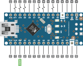
Aref
Reference voltage for the analogue inputs.
Interrupt
INT0 and INT1. Arduino® Nano has two external interrupt pins. An external interrupt is a system interrupt that occurs when outside interference is present. Interference can come from the user or other hardware devices in the network. Common uses for these interrupts in Arduino are reading the frequency of a square wave generated by encoders or waking up the processor upon an external event.
Arduino has two forms of interrupt:
- External
- Pin Change
There are two external interrupt pins on the ATmega168/328 called INT0 and INT1. Both INT0 and INT1 are mapped to pins 2 and 3. In contrast, Pin Change interrupts can be activated on any of the pins.
ICSP Header
ICSP stands for In-Circuit Serial Programming. The name originated from In-System Programming headers (ISP). Manufacturers like Atmel who work with Arduino have developed their own in-circuit serial programming headers. These pins enable the user to program the Arduino boards’ firmware. There are six ICSP pins available on the Arduino board that can be hooked to a programmer device via a programming cable.
Overview
The Arduino® Nano Microcontroller is one of the most versatile boards on the market today, and that’s why we decided to focus on it in this guide. This guide displays most of its capabilities, but there are also more advanced options, which we did not go into in this post.
The important thing to know when you choose a board for your project is its capabilities and limitations. It’s also important to understand the different communication protocols that the board uses. Of course, you don’t need to remember all of this information, you can always go back to this post and read the relevant information for you (this is a good time to bookmark this Blog btw).
Download
Download the Arduino® Nano Reference sheet for free!
Link:https://www.studiopieters.nl/arduino-nano-pinout/