Introduction
Arduinos are great for many reasons, one of them being their ability to wire up to almost anything. But there are times when you want to connect to your Arduino without using any wires, and when you do get the desire to go wireless there are several methods to choose from.
In this article (and in the corresponding video) I will examine one method of Arduino wireless communications, the nRF24L01+ module. This is an inexpensive module that provides 2-way communications using the 2.4 GHz band. This band is free to use for low power devices without a license and in some cases can be useful up to a kilometer (although you should expect much shorter ranges without a special antenna).
The nRF24L01+ is available in a number of different configurations, in this article I’ll look at a couple of the more popular ones. We’ll hook them up and use a very extensive library to facilitate communications between them.

After we get them working we will use them to build something fun – a wireless joystick control for the Robot Car Base that we worked on earlier.
Before we begin let’s examine the nRF24L01+ and some of the factore you need to take into account when designing wireless devices.
Wireless Communications
We have been sending information wirelessly since the late 1880’s, Thomas Edison used a system of Electromagnetic Induction to send telegraph signals from a moving train to a set of wires beside the track. Wireless devices are pretty well a part of our lives and most work using one of the following methods:
- Signals are sent on beams of infrared light
- Signals are sent using radio waves
Radio waves have a number of advantages over beams of infrared light, the most obvious is that radio waves can travel (to a degree) through walls and most other obstructions.
Radio waves are by no means a perfect method of communication, they are subject to interference from a number of sources and can be obstructed by metal or thick walls. But they do serve their purpose in a number of low-speed data applications and are thus perfect or Arduino and Raspberry Pi experimenters who want to build remote controlled devices or who need to send data without wires.
Radio signals are based upon the concept of changing or “modulating” a “carrier wave” that is transmitted wirelessly to a receiver. On the receiving end the carrier wave is stripped off and the signal is “demodulated” to extract the original information from it.
Since these carrier waves can interfere with one another the allotment of them is strictly controlled, and every nation has a government department responsible for regulating them. In the United States it’s the Federal Communications Commission (FCC), in Canada it’s the Canadian Radio and Television Commission (CRTC) and in the UK the radio waves are regulated by the Office of Communications (Ofcom). Using radio carrier frequencies illegally can result in a very stiff fine and is also pretty rude, so just don’t do it.
There are plenty of frequencies available to experimenters like us, one of the most popular is the 2.4 GHz Band.
The 2.4 GHz Band
The 2.4 GHz Industrial, Scientific and Medical (ISM) band has been reserved for unlicensed low-powered devices and this makes it perfect for building remotely controlled Arduino devices. Of course it also makes it perfect for a number of other devices in your house like wireless routers, cordless phones, Bluetooth gizmos and other wireless dodadds.
The band in question runs from 2.400.0 GHz to 2.483.5 GHz and in order to make it possible for multiple devices to coexist it’s broken down into channels. Although there are 14 channels available not every one is legal in every area. Channels 1 to 11 are legal in most every part of the world so you’d be advised to contain your experimenting to those channels.
As communicating on the 2.4 GHz band is a pretty common function there are a number of modules made for exactly that purpose. The one we will be playing with today is possibly the most popular, it’s available for a couple of dollars or less on eBay and Amazon.
The nRF24L01+
The nRF24L01+ is the part number of a common chip used to construct 2.4 GHz transmitters and receivers, or “transceivers”. This chip has been used to create some simple and inexpensive modules that can be used to transmit and receive data using the 2.4 GHz band.
There are a variety of modules available based upon the nRF24L01, I’m going to use two very common ones in this article. If you have a different module it should work fine, just be sure to observe the wiring and especially the power supply requirements.
<INSERT NRF24L01 2 Modules PICTURE>
The two modules I’m using are quite similar and are interchangeable, the difference between them is that one of them has a built in Low Noise Amplifier (LNA) and an external antenna connection. I tend to prefer that one even though it’s a bit more expensive as it can be used for reliable data communications over a pretty fair distance. Unless you live in a castle it will probably be more than sufficient to cover your entire house.
All of the experiments, including the wireless joystick, may be built with either module (they share the same pinouts) but you’ll achieve better range with the model with the external antenna.
nRF24L01 Connections
The nRF24L01 has an 8-pin connector that interfaces it with the outside world. This connector is common between both styles of nRF24L01 modules. Although the nRF24L01 is powered by a 1.9 to 3.9 volt supply the logic pins are 5-volt tolerant so they can be used directly with an Arduino or other 5-volt logic microcontroller.
SPI Bus
The nRF24L01 communicates using the Serial Peripheral Interface or SPI bus. This is a standard bus that is used by many microcontrollers and microcomputers including the Arduino and the Raspberry Pi.
The SPI bus uses a concept of a Master and Slave, in most common applications the microcontroller or microcomputer is the Master and the nRF24L01 is the Slave. Unlike the I2C bus the number of slaves on the SPI bus is limited, on the Arduino Uno you can use a maximum of two SPI slaves.
The SPI bus is a bidirectional bus, meaning that the master and slave can transmit and receive simultaneously, however the library we will be using with the nRF24L01 doesn’t do that.
Each slave device needs to be selected by the master in order for it to communicate. Only one slave can communicate at any given time. The nRF24L01 and other slave devices have an Interrupt pin that can alert the master when they need to communicate but the library we will be using today ignores that so in our applications we won’t be connecting the interrupt pin to the Arduino.
Module Connections
The connections to the nRF24L01 module are as follows:

- GND. This is the Ground Pin. It is usually marked by encasing the pin in a square so it can be used as a reference for identifying the other pins.
- VCC. The positive voltage. This can be anywhere from 1.9 to 3.9 volts. It os NOT 5-volt tolerant!
- CE. Chip Enable, an active-high pin. When selected the nRF24L01 will either transmit or receive, depending upon which mode it is currently in.
- CSN. Chip Select Not. Thi is an active-low pin, it is the pin that the SPI bus uses to select the nRF24L01 slave.
- SCK. The Clock pin, an external clock source provided by the SPI bus Master.
- MOSI. Master Out Slave In. The input to the nRF24L01.
- MISO. Master In Slave Out. The output from the nRF24L01.
- IRQ. The Interrupt output pin.
The style of nRF24L01 that uses an external antenna also has an SMA connector for attaching the antenna.
Power Supply Considerations
Because the nRF24L01 has a power supply range of 1.9 – 3.9 volts it can be battery powered. It is also common to power the module with a 3.3 volt power supply.
When selecting a power supply it should be noted that the nRF24L01 can consume a fair amount of current when transmitting at its highest power. Your power supply should be capable of providing at least 300 mA of current.
Noise on the power supply can also cause problems with the nRF24L01. It is advised to place a filter capacitor (100 microfarads is ideal) across the power supply lines as physically close to the nRF24L01 module as possible to eliminate power supply noise.
Another way to resolve the power supply issues, and the one I suggest you employ, is to use an Adapter Module for your nRF24L01.
nRF24L01 Adapter Module
The nRF24L01 Adapter Module is a very inexpensive prototyping board that simplifies working with the nRF24L01. I recommend you use one and I show it in all the schematics included in this article.
The adapter module has an 8-pin female connector to allow you to plug in an nRF24L01, it can accommodate either the module with the =integrated or external antenna. It also has a 6-pin male connector for the SPI and Interrupt connections and a 2-pin connector for power input.
The adapter module has its own 3.3 volt voltage regulator and a set of filter capacitors, so you can power it with a 5-volt power supply. Assuming your power supply has the required current capability the adapter module will resolve all of the power supply considerations mentioned above.
Since these modules are available for about a dollar a piece there is no real reason why you shouldn’t use one. They can make the difference between success and failure with your nRF24L01 design.
nRF24L01+ and Arduino
In our experiments we will be using two nRF24L01 modules with a couple of Arduino Unos. You could of course use another model of Arduino, if you do however you may need to change the pinouts as different Arduino models use different pins for the SPI bus.
I’ll describe the pinouts for both the Arduino Uno and the Arduino Mega 2560 here. Going forward (in in the schematics) I’ll only be using an Arduino Uno so if you are using a Mega 2560 you’ll need to substitute pin numbers accordingly. Our Robot Car project was based around an Arduino Uno, this is the project that we will be modifying to use the wireless joystick with.
Arduino Libraries and Connections
As with other radio modules there are a number of libraries available for the nRf24l)1. Using a library will really simplify creating projects with these modules.
The following libraries will all work with the nRF24L01+ modules:
- TMRh20 – This library has been around for several years. It is great for creating secure wireless communications devices. You can read more on the TMRh20 Project Blog and get the latest version on the TMRh20 GitHub repository fork for Arduino devices.
- RF24 – This is an old standard and has been used in many nRF24L01 projects. It has been superseded by the RadioHead and TMRh20 libraries.
- Mirf Library – Based on the Tinkerer library. This is a much older library so you won’t find too many projects based upon it anymore.
- RadioHead – This is a modern library with many advanced features, capable of supporting many RF modules.
In the experiments we will be performing and for our wireless joystick project we will be using the RadioHead library.
Please note that not all of the libraries listed above use the came connections to the Arduino, and that the connections differ depending upon which type of Arduino you are using.
RadioHead Library
RadioHead is a library written by Mike McCauley for the Airspayce company. I used it in a previous article, Using Inexpensive 433MHz Transmit and Receive Modules with Arduino.
This is an advanced library which allows many methods of packet radio communications between RF modules like the nRF24L01. It contains many different drivers for different RF modules, the driver for the nRF24L01 is the RH_NRF24 driver.
You can learn more about the RadioHead library and download the ZIP file that you will need to install in in your Arduino IDE on the RadioHead website. Look for the link to the ZIP file near the top of the description on the page.
Once you download the ZIP file you will need to install it in your Arduino IDE. This is a very simple process:
- Open the Arduino IDE.
- Select Sketch from the top menu bar,
- Select Include Library from the Sketch menu drop-down.
- Select Add .ZIP Library from the Include Library sub-menu.
- Use the dialog box to select the ZIP file you have downloaded.
- The RadioHead library will be installed.
After you have the RadioHead library installed in your Arduino IDE you are ready to begin the experiments with the nRF24L01.
Hooking up the Arduinos
The RadioHead library comes with a number of sample sketches that illustrate its use. We will begin our experiments with a few of these sketches, then we’ll modify a couple of them for our joystick project.
Here are the connections you will need to make for an Arduino Uno:

Note that you will need to make two of these circuits! We will refer to one of the circuits as the Server and one as the Client. The wiring for both is identical.
Also note that I’m illustrating the schematic using a nRF24L01 Adapter Module which has its own voltage regulator to supply the 3.3 volts to the nRF24L01. You can wire directly to the nRF24L01 itself if you wish but you’ll need to use the 3.3 volt output from your Arduino and not the 5 volt output (which will likely destroy your nRF24L01 module).
Note that many Arduino clones don’t have sufficient current on the 3.3 volt output for the nRF24L01. Even if yours does it’s advisable to use a filter capacitor across the power supply lines. But again your best bet is to simply use the nRF24L01 Adapter Module and save yourself a lot of grief and frustration!
If you are using an Arduino Mega 2560 then the pinouts for the RadioHead library are a bit different:
- GND. This is still Ground of course so it goes to one of the Mega 2560 ground pins.
- VCC. Again this is still a power supply connection. See the notes above regarding which voltage to use.
- CE. This is the same as the Arduino Uno, it goes to pin 8 on the Mega 2560.
- CSN. Connect this to output pin 53 on the Mega 2560.
- SCK. Connect this to output pin 52 on the Mega 2560.
- MOSI. This goes to pin 51 on the Mega 2560.
- MISO. Finally this goes to pin 50 on the Mega 2560.
Note that the IRQ pin on the nRF24L01 is not used with either of the Arduino boards as it’s ignored by the RadioHead library.
Once you have everything hooked up you are ready to run the first sketches.
RadioHead Sample Sketch – Client & Server
The first sketches we will be running are the basic client and server examples included with the RadioHead library. You can find and load them as follows:
- Open the Arduino IDE (you may have already done this).
- Open the File menu from the top menu bar.
- Select Examples. A sub-menu will be displayed.
- Scroll down the Examples sub-menu to the section at the bottom titled Examples from Custom Libraries.
- Select RadioHead from the menu. Another sub-menu will appear beside this one.
- Select nrf24 from the RadioHead sub-menu.
- A list of example sketches for the RadioHead RH_NRF24 Driver will be displayed.
There are two sketches we need to load, one on each Arduino. If you don’t have the luxury of having two computers then you can do these individually using one computer.
The sketches we need are as follows:
- On the Server Arduino load the nrf24_server sketch.
- On the Client computer load the nrf24_client sketch.
The sketches are very well commented so I’ll just go over some of the essential elements of the here.
Each sketch includes the RadioHead RH_NRF24 library as well as the Arduino SPI library. They both then declare an instance of the radio driver. If you want to change the wiring or use a different type of Arduino you can add optional parameters when declaring the driver.
After that they both move into the Setup routine, which begins by setting up the serial monitor and initializing the driver. Afterwards the setChannel method is called to change the radio channel from the default channel (which is channel 2) to channel 1. You can experiment with different channels if you find any 2.4 GHz devices you have (i.e wireless mice) interfere with the experiment.
You can also add parameters to change the data rate and transmit power of the module. A slower data rate will result in a longer range of operation. Just be sure to keep the data rate and channel the same between the server and client.
We then proceed to the loop.
On the server side the loop starts by looking for a message from the client. If it is received it is placed into a buffer and then printed to the serial monitor. After that a reply “And hello back to you” is placed into an array and is sent to the client.
On the client side the loop begins in the opposite fashion. A message “Hello World” is placed into an array and is sent to the server. We then wait to receive a message from the client (the “And hello back to you” message). If/when we receive the message it gets printed out to the serial monitor.
If you are lucky enough to have two computers you can open both serial monitor and observe the interaction between the server and client. If you only have one computer then I suggest you power one Arduino with a battery or USB power supply while you use your computer to power and monitor the other one.
While this is a very basic sketch it does illustrate how the RadioHead library makes it easy to work with the nRF24L01. And it also has a practical use – you can use it (with one Arduino battery powered) to determine the range you can achieve with your two modules. If you have both the modules with integrated antennas and the ones with external antennas you’ll soon see how vastly superior the external antenna modules really are.
RadioHead Sample Sketch – Reliable Datagram
The previous sketches work well and for many applications they are all you’ll ever need. But if you have a situation where you’re transmitting data that simply must be received without errors then you’ll want to look at another method.
This can be a requirement when you are breaking up a large file into several small bits. The transmitting end needs to make sure that the receiving end has received every bit intact. If it isn’t then the data needs to be resent.
Data transfer on the Internet works using this principle.
The RadioHead Reliable Datagram method of exchanging data also uses this method of verifying data integrity. It doesn’t require any special coding on either end as the Reliable Datagram library does it all for you in the background. Let’s look at it now.
For this experiment you won’t need to make any wiring changes as the hookup is identical to the previous experiment.
Go back into the RadioHead Library Example sketches for nrf24 and select the following two sketches:
- On the Server Arduino load the nrf24_reliable_datagram_server sketch.
- On the Client Arduino load the nrf24_reliable_datagram_client sketch.
Again these sketches are well commented and they also have many similarities to the sketches we just looked at, so I’ll mostly discuss the differences here.
Aside from the two libraries loaded in the previous sketches these sketches also load the RadioHead RHReliableDatagram library.
Afterwards two constants are defined, a CLIENT_ADDRESS and SERVER_ADDRESS. These addresses are not radio channels, instead they are addresses used within the datagram packets exchanged between the server and client.
After creating an instance of the radio driver each sketch set up a datagram manager using one of the addresses defined above (this is where the server and client differ).
In the setup routine the serial monitor is setup and the datagram manager is initialized.
Outside of the setup routine and before the loop an array is defined with the data to be sent and a buffer is defined.
In the loop the operation is very similar to the previous sketches. The server waits for a message to be received from the client, prints it to the serial monitor and then sends a message of its own. The client does the same in reverse.
One thing you will notice in the serial monitor is that both sides print out the address contained in the received packet.
Try out the demo and see the results. At far range you’ll occasionally notice a slight delay in receiving data, this will occur when packets drop off and need to be resent.
As with the previous sketches this one works very well. We will modify this sketch now to send some joystick data and then use it to build our wireless joystick.
Joystick Demo
The two previous sets of sketches illustrated how to exchange text data like “Hello World” and “And hello back to you”, which in itself can be useful. But in many situations you’ll want to exchange numerical data wirelessly between two Arduinos. An example of this would be sending data from a remote sensor to a base station.
In our next experiment we will send data from a joystick to the remote receiver. Each axis of the joystick will be sent as as single byte along with a “dummy byte” whose use I will explain in due time. Depending upon the position of the joystick the values of the axis data wil range from 0 to 255.
You can of course use this sketch to send other sensor data, it doesn’t need to be from a joystick. Your imagination is the only limitation here.
Each sketch is a modified version of the Reliable Datagram sketches we saw earlier, you’ll recognize a lot of the code. No sense in reinventing the wheel!
Before we get started you’ll need to take one of the Arduinos and add a joystick to it. The hookup is shown below:

As you can see the joystick hookup is very simple. If you don’t have a joystick just use two potentiometers as that’s really all that an analog joystick is – a pot for the x-axis and another one for the y-axis. Each control is connected to one of the Arduino’s analog inputs.
On the other end just leave the Arduino and nRF24L01 wired as they are, the only thing you’ll need to change is the sketch.
Here is the sketch for the joystick side of things. Note that it is based upon the RadioHead Reliable Datagram Client sketch, that was just an arbitrary choice on my part as I could have just as easily used the server sketch.
/*
  nRF24L01+ Joystick Transmitter
  nrf24l01-joy-xmit-demo.ino
  nRF24L01+ Transmitter with Joystick
  Use with Joystick Receiver Demo
  DroneBot Workshop 2018
  https://dronebotworkshop.com
*/

// Include RadioHead ReliableDatagram & NRF24 Libraries
#include <RHReliableDatagram.h>
#include <RH_NRF24.h>

// Include dependant SPI Library
#include <SPI.h>

// Define Joystick Connections
#define JoyStick_X_PIN     A0
#define JoyStick_Y_PIN     A1

// Define addresses for radio channels
#define CLIENT_ADDRESS 1
#define SERVER_ADDRESS 2

// Create an instance of the radio driver
RH_NRF24 RadioDriver;

// Sets the radio driver to NRF24 and the client address to 1
RHReliableDatagram RadioManager(RadioDriver, CLIENT_ADDRESS);

// Declare unsigned 8-bit joystick array
uint8_t joystick[3];

// Define the Message Buffer
uint8_t buf[RH_NRF24_MAX_MESSAGE_LEN];

void setup()
{
  // Setup Serial Monitor
  Serial.begin(9600);

  // Initialize RadioManager with defaults - 2.402 GHz (channel 2), 2Mbps, 0dBm
  if (!RadioManager.init())
    Serial.println("init failed");
}

void loop()
{
  // Print to Serial Monitor
  Serial.println("Reading joystick values ");

  // Read Joystick values and map to values of 0 - 255
  joystick[0] = map(analogRead(JoyStick_X_PIN), 0, 1023, 0, 255);
  joystick[1] = map(analogRead(JoyStick_Y_PIN), 0, 1023, 0, 255);
  joystick[2] = 100;

  //Display the joystick values in the serial monitor.
  Serial.println("-----------");
  Serial.print("x:");
  Serial.println(joystick[0]);
  Serial.print("y:");
  Serial.println(joystick[1]);

  Serial.println("Sending Joystick data to nrf24_reliable_datagram_server");

  //Send a message containing Joystick data to manager_server
  if (RadioManager.sendtoWait(joystick, sizeof(joystick), SERVER_ADDRESS))
  {
    // Now wait for a reply from the server
    uint8_t len = sizeof(buf);
    uint8_t from;
    if (RadioManager.recvfromAckTimeout(buf, &len, 2000, &from))
    {
      Serial.print("got reply from : 0x");
      Serial.print(from, HEX);
      Serial.print(": ");
      Serial.println((char*)buf);
    }
    else
    {
      Serial.println("No reply, is nrf24_reliable_datagram_server running?");
    }
  }
  else
    Serial.println("sendtoWait failed");

  delay(100);  // Wait a bit before next transmission
}
The sketch starts in the same way as the RadioHead Reliable Datagram sketches, it loads the required libraries. We also define the inputs used by the joystick, as well as client and server addresses for the reliable datagram packets.
We then define an 8-bit unsigned integer array called “joystick” with three elements:
- joystick[0] is the x-axis value.
- joystick[1] is the y-axis value.
- joystick[2] is the “dummy” value.
The only reason for sending the “dummy” value is to have a third byte as our final wireless joystick sketch will use this byte to indicate the motor direction. By defining it in this demonstration sketch we can use the receiver we build here to troubleshoot the final product if necessary.
I assigned a value of 100 to the dummy value, you can assign pretty well any value between 0 and 255. It’s just there to test data integrity right now.
The setup routine is identical to the RadioHead Reliable Datagram example.
In the loop we start the serial monitor as we will use it to monitor joystick values. We then proceed to get those joystick values using an Arduino analogRead function on each of the joystick analog inputs.
As the Arduino’s analog to digital converter is a 10-bit converter we will get a value of 0 to 1023 back from each joystick. We use the Arduino map command to convert this into a range of 0 to 255. Each of the hvalues is assigned to its respective element in the joystick array.
The remainder of the sketch is pretty well identical to the Reliable Datagram sketch. The array is sent to the server end and we wait to see if we get a reply. Then we do it all over again.
The other end (i.e. the “joystick receiver”) is even simpler. Here is the sketch:
/*
  nRF24L01+ Joystick Receiver Demo
  nrf24l01-joy-rcv-demo.ino
  nRF24L01+ Receiver with Joystick Decode
  Use with Joystick Transmitter Demo
  DroneBot Workshop 2018
  https://dronebotworkshop.com
*/

// Include RadioHead ReliableDatagram & NRF24 Libraries
#include <RHReliableDatagram.h>
#include <RH_NRF24.h>

// Include dependant SPI Library
#include <SPI.h>

// Define addresses for radio channels
#define CLIENT_ADDRESS 1
#define SERVER_ADDRESS 2

// Create an instance of the radio driver
RH_NRF24 RadioDriver;

// Sets the radio driver to NRF24 and the server address to 2
RHReliableDatagram RadioManager(RadioDriver, SERVER_ADDRESS);

// Define a message to return if values received
uint8_t ReturnMessage[] = "JoyStick Data Received";

// Define the Message Buffer
uint8_t buf[RH_NRF24_MAX_MESSAGE_LEN];

void setup()
{
  // Setup Serial Monitor
  Serial.begin(9600);

  // Initialize RadioManager with defaults - 2.402 GHz (channel 2), 2Mbps, 0dBm
  if (!RadioManager.init())
    Serial.println("init failed");
}

void loop()
{
  if (RadioManager.available())
  {
 // Wait for a message addressed to us from the client
    uint8_t len = sizeof(buf);
    uint8_t from;
    if (RadioManager.recvfromAck(buf, &len, &from))
 //Serial Print the values of joystick
    {
      Serial.print("got request from : 0x");
      Serial.print(from, HEX);
      Serial.print(": X = ");
      Serial.print(buf[0]);
      Serial.print(" Y = ");
      Serial.print(buf[1]);
      Serial.print(" Z = ");
      Serial.println(buf[2]);

      // Send a reply back to the originator client, check for error
      if (!RadioManager.sendtoWait(ReturnMessage, sizeof(ReturnMessage), from))
        Serial.println("sendtoWait failed");
    }
  }
}
The only difference between this sketch and the RadioHead Reliable Datagram server sketch is that we are displaying numerical values in the received data array instead of text. We label these as X, Y and Z:
- X is the x-axis reading.
- Y is the y-axis reading.
- Z is the “dummy value”.
After loading bnoth sketches run them, with at least the receiver connected to a computer so you can observe the serial monitor. You should observe the values change as you move the joystick.
Robot Car Remote
So now we can see how we can send joystick values. It’s time to put it all together and create our Robot Car remote joystick.
On the joystick side you have already done the wiring, all you’ll need to change is the sketch. On the other end though you’ll need a robot car!
If you followed the instructions in the previous article “Build a Robot Car with Speed Sensors” then you already have a robot car. If not then go and see that article for instructions on putting together a robot car using an inexpensive kit.
As this project doesn’t use the speed sensors you can ignore that part. If you already have built the robot car then just leave it as it is, you don’t need to remove the speed sensors.
If you did build the original car there are some changes you will need to make, specifically in how the L298N H-Bridge motor controller is hooked up. The original design uses some of the pins required by the nRF24L01 so it needs to be required.
Here is the new Robot Car schematic:

The connections to the nRF24L01 module are exactly the same as they have been in our other experiments, no surprise there. You can use any type of nRF24L01 module but I strongly recommend using the model with the external antenna for improved performance, at least on the car side.
Using an Analog Pin as a Digital Pin
On the motor side you’ll notice that the pins for Motor A have been moved when compared to the original design. One of them might surprise you – the L289N H-Bridge IN1 pin is connected to the Arduino analog pin A0. Why an analog pin?
If you look at the specs of the ATMega328, which is the heart of the Arduino Uno, you’ll understand why I used A0. It turns out the the “analog” pins on an Arduino can also function quite well as digital I/O pins.
I needed an extra pin for my L298N motor controller and I had a few choices:
- I didn’t want to use pins 2 or 3 as the Robot Car uses these for the speed sensors. Even though the sensors are not part of this design I wanted to keep them free.
- Pins 1 and 2 might look promising but they are also special pins – they are used as the RX and TX lines for the serial interface. I wanted to keep them free, also due to internal reasons they won’;t work very well in this application anyway.
- I chose to use pin A0. Its and analog pin but it’s also digital I/O pin #14 on the Arduino Uno.
As long as the pin is defined as an output in code it will work fine.
Once you have the car wired up all that remains is to load the code. We will look at the joystick code first.
Joystick Transmitter Sketch
As you might expect the remote joystick sketch is very similar to the joystick demo sketch we looked at earlier. Her it is in all its glory:
/*
  nRF24L01+ Joystick Transmitter
  nrf24l01-joy-xmit-car.ino
  nRF24L01+ Transmitter with Joystick for Robot Car
  Use with Joystick Receiver for Robot Car
  DroneBot Workshop 2018
  https://dronebotworkshop.com
*/

// Include RadioHead ReliableDatagram & NRF24 Libraries
#include <RHReliableDatagram.h>
#include <RH_NRF24.h>

// Include dependant SPI Library
#include <SPI.h>

// Define Joystick Connections
#define joyVert    A0
#define joyHorz    A1

// Define Joystick Values - Start at 512 (middle position)
int joyposVert = 512;
int joyposHorz = 512;

// Define addresses for radio channels
#define CLIENT_ADDRESS 1
#define SERVER_ADDRESS 2

// Create an instance of the radio driver
RH_NRF24 RadioDriver;

// Sets the radio driver to NRF24 and the client address to 1
RHReliableDatagram RadioManager(RadioDriver, CLIENT_ADDRESS);

// Declare unsigned 8-bit motorcontrol array
// 2 Bytes for motor speeds plus 1 byte for direction control
uint8_t motorcontrol[3];

// Define the Message Buffer
uint8_t buf[RH_NRF24_MAX_MESSAGE_LEN];

void setup()
{
  // Setup Serial Monitor
  Serial.begin(9600);

  // Initialize RadioManager with defaults - 2.402 GHz (channel 2), 2Mbps, 0dBm
  if (!RadioManager.init())
    Serial.println("init failed");

  // Set initial motor direction as forward
  motorcontrol[2] = 0;

}

void loop()
{
  // Print to Serial Monitor
  Serial.println("Reading motorcontrol values ");

  // Read the Joystick X and Y positions
  joyposVert = analogRead(joyVert);
  joyposHorz = analogRead(joyHorz);

  // Determine if this is a forward or backward motion
  // Do this by reading the Verticle Value
  // Apply results to MotorSpeed and to Direction

  if (joyposVert < 460)
  {
    // This is Backward
    // Set Motors backward
    motorcontrol[2] = 1;

    //Determine Motor Speeds
    // As we are going backwards we need to reverse readings
    motorcontrol[0] = map(joyposVert, 460, 0, 0, 255);
    motorcontrol[1] = map(joyposVert, 460, 0, 0, 255);

  }
  else if (joyposVert > 564)
  {
    // This is Forward
    // Set Motors forward
    motorcontrol[2] = 0;

    //Determine Motor Speeds
    motorcontrol[0] = map(joyposVert, 564, 1023, 0, 255);
    motorcontrol[1] = map(joyposVert, 564, 1023, 0, 255);

  }
  else
  {
    // This is Stopped
    motorcontrol[0] = 0;
    motorcontrol[1] = 0;
    motorcontrol[2] = 0;

  }

  // Now do the steering
  // The Horizontal position will "weigh" the motor speed
  // Values for each motor

  if (joyposHorz < 460)
  {
    // Move Left
    // As we are going left we need to reverse readings
    // Map the number to a value of 255 maximum
    joyposHorz = map(joyposHorz, 460, 0, 0, 255);

    motorcontrol[0] = motorcontrol[0] - joyposHorz;
    motorcontrol[1] = motorcontrol[1] + joyposHorz;

    // Don't exceed range of 0-255 for motor speeds
    if (motorcontrol[0] < 0)motorcontrol[0] = 0;
    if (motorcontrol[1] > 255)motorcontrol[1] = 255;

  }
  else if (joyposHorz > 564)
  {
    // Move Right
    // Map the number to a value of 255 maximum
    joyposHorz = map(joyposHorz, 564, 1023, 0, 255);

    motorcontrol[0] = motorcontrol[0] + joyposHorz;
    motorcontrol[1] = motorcontrol[1] - joyposHorz;

    // Don't exceed range of 0-255 for motor speeds
    if (motorcontrol[0] > 255)motorcontrol[0] = 255;
    if (motorcontrol[1] < 0)motorcontrol[1] = 0;

  }

  // Adjust to prevent "buzzing" at very low speed
  if (motorcontrol[0] < 8)motorcontrol[0] = 0;
  if (motorcontrol[1] < 8)motorcontrol[1] = 0;

  //Display the Motor Control values in the serial monitor.
  Serial.print("Motor A: ");
  Serial.print(motorcontrol[0]);
  Serial.print(" - Motor B: ");
  Serial.print(motorcontrol[1]);
  Serial.print(" - Direction: ");
  Serial.println(motorcontrol[2]);

  //Send a message containing Motor Control data to manager_server
  if (RadioManager.sendtoWait(motorcontrol, sizeof(motorcontrol), SERVER_ADDRESS))
  {
    // Now wait for a reply from the server
    uint8_t len = sizeof(buf);
    uint8_t from;
    if (RadioManager.recvfromAckTimeout(buf, &len, 2000, &from))
    {
      Serial.print("got reply from : 0x");
      Serial.print(from, HEX);
      Serial.print(": ");
      Serial.println((char*)buf);
    }
    else
    {
      Serial.println("No reply, is nrf24_reliable_datagram_server running?");
    }
  }
  else
    Serial.println("sendtoWait failed");

  delay(100);  // Wait a bit before next transmission
}
Those of you who went through the “Controlling DC Motors with the L298N Dual H-Bridge and an Arduino” article may recognize some of the code here as it’s taken from the sketch I used to demo a joystick with a robot car (that one used a wire).
We start by defining our libraries as we did before. Then we define the analog pins used for the joystick inputs as well as a couple of variables that hold values of those inputs.
The real difference in this sketch is what we do with those values. We want the joystick to operate as follows:
- If we push the joystick forward the car should go forward. The further we push it the faster it should go.
- If we pull the joystick back towards us the car should run in reverse. The further we pull it back the faster it should go.
- If we move it to the left the car should steer left.
- If we move it to the right the car should steer right.
- If we leave the joystick in the center position then the car should not move at all.
I established the “middle” of both the horizontal and vertical travel of the joystick to have values between 460 and 564. The exact middle would of course be 511.5 but we are using integers and we also have to consider that two dollar joysticks are not the most precision instruments available.
If you follow the sketch through you should see the logic in this. We determine if the vertical joystick is above 564 and if it is we are going to drive forward. So we set the motorcontrol[2] variable to a value of 0, which in this sketch means “forward”.
If our vertical joystick is below 460 then we set motorcontrol[2] to 1 to indicate we want to go backwards.
We then use the Arduino map function to map the joystick values to a value in the 0 to 255 range for the motor speeds, which are assigned to the motorcontrol[0] and motorcontrol[1] variables.
The horizontal control functions in the same manner, except it applies an offset to the speed values to make one motor spin faster than the other one.
We then send the three variables in the array off to the transmitter, just like we did in the joystick demo sketch.
Joystick Receiver Sketch
The receiver sketch, the one that runs on the car itself, is actually pretty simple. Here it is:
/*
  nRF24L01+ Joystick Receiver for Robot Car
  nrf24l01-joy-rcv-car.ino
  nRF24L01+ Receiver and L298N driver for Robot Car
  Use with Joystick Transmitter for Robot Car
  DroneBot Workshop 2018
  https://dronebotworkshop.com
*/

// Include RadioHead ReliableDatagram & NRF24 Libraries
#include <RHReliableDatagram.h>
#include <RH_NRF24.h>

// Include dependant SPI Library
#include <SPI.h>

// Define addresses for radio channels
#define CLIENT_ADDRESS 1
#define SERVER_ADDRESS 2

// Motor A Connections
int enA = 9;
int in1 = 14;
int in2 = 4;

// Motor B Connections
int enB = 5;
int in3 = 7;
int in4 = 6;

// Create an instance of the radio driver
RH_NRF24 RadioDriver;

// Sets the radio driver to NRF24 and the server address to 2
RHReliableDatagram RadioManager(RadioDriver, SERVER_ADDRESS);

// Define a message to return if values received
uint8_t ReturnMessage[] = "JoyStick Data Received";

// Define the Message Buffer
uint8_t buf[RH_NRF24_MAX_MESSAGE_LEN];

void setup()
{
  // Setup Serial Monitor
  Serial.begin(9600);

  // Set all the motor control pins to outputs
  pinMode(enA, OUTPUT);
  pinMode(enB, OUTPUT);
  pinMode(in1, OUTPUT);
  pinMode(in2, OUTPUT);
  pinMode(in3, OUTPUT);
  pinMode(in4, OUTPUT);

  // Initialize RadioManager with defaults - 2.402 GHz (channel 2), 2Mbps, 0dBm
  if (!RadioManager.init())
    Serial.println("init failed");
}

void loop()
{
  if (RadioManager.available())
  {
 // Wait for a message addressed to us from the client
    uint8_t len = sizeof(buf);
    uint8_t from;
    if (RadioManager.recvfromAck(buf, &len, &from))

    {

      //Serial Print the values of joystick
      //Serial.print("got request from : 0x");
      //Serial.print(from, HEX);
      //Serial.print(": MotorA = ");
      //Serial.print(buf[0]);
      //Serial.print(" MotorB = ");
      //Serial.print(buf[1]);
      //Serial.print(" Dir = ");
      //Serial.println(buf[2]);

      // Set Motor Direction
      if (buf[2] == 1)
      {
    // Motors are backwards
    digitalWrite(in1, LOW);
    digitalWrite(in2, HIGH);
    digitalWrite(in3, LOW);
    digitalWrite(in4, HIGH);
    }else{
    // Motors are forwards
    digitalWrite(in1, HIGH);
    digitalWrite(in2, LOW);
    digitalWrite(in3, HIGH);
    digitalWrite(in4, LOW);
     }


      // Drive Motors
      analogWrite(enA, buf[1]);
      analogWrite(enB, buf[0]);

      // Send a reply back to the originator client, check for error
      if (!RadioManager.sendtoWait(ReturnMessage, sizeof(ReturnMessage), from))
        Serial.println("sendtoWait failed");
    }
  }
}
Essentially this is the same receiver sketch we have used in the last demo with the addition of variables to define the motor connections. Note that we use Arduino pin “14” for variable in1, this is of course the analog A0 pin. You could actually substitute an “A0” here if you wish and it will work just fine.
In the setup we define the motor controller pins as outputs. Note that the pins used for the two L298N enable lines need to be capable of PWM as that’s how the motor speed is regulated.
You may notice I have remarked out all of the serial monitor statements. They are not really necessary and just get in the way when the car is operating but you can “unremark” if you need to troubleshoot your car.
The buffer values correspond to the motor control values we used in the transmitter. So buf[2] contolas the motor direction and buf[0] and buf[1] handle the motor speeds.
The motors are controlled with PWM using the Arduino analogWrite function.
Load the sketches and fire everything up. You should now have a remote controlled robot car!
Conclusion
As you can see the nRF24L01 can be used to create some very useful wireless projects with very little code, thanks to the RadioHead library. If building robot cars isn’t your thing you can still find a lot of use for this powerful combination, and I’ll be featuring some more projects using these devices very soon.
Until then enjoy your robot car and happy motoring!
Parts List
Here are some components that you might need to complete the experiments in this article. Please note that some of these links may be affiliate links, and the DroneBot Workshop may receive a commission on your purchases. This does not increase the cost to you and is a method of supporting this ad-free website.
COMING SOON!
Resources
Sketches for the Article. All of the sketches used in this article in a very handy ZIP file, just for you!
RadioHead Library. You will need the RadioHead Library for Arduino to run the experiments in this article.
nRF24L01 How-To. This is an excellent resource from the Arduino Info blog that tells you a LOT about the nRF24L01.
Project Arduino Nano
Materials:-
Arduino NANO
NRF24L01 Transceiver
Joystick Module
L298N Motor Driver
BreadBoard
18650 Battery
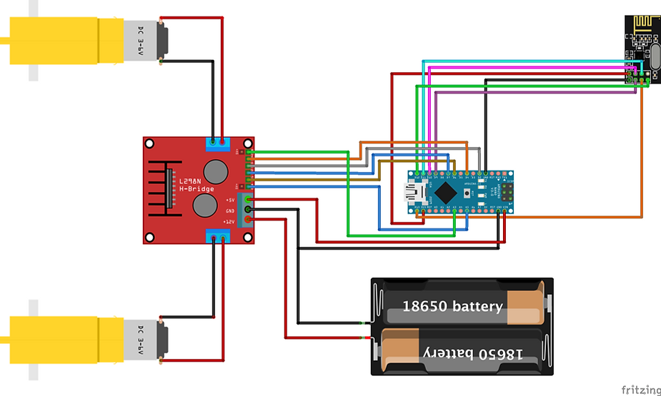
Circuit:-
Transmitter

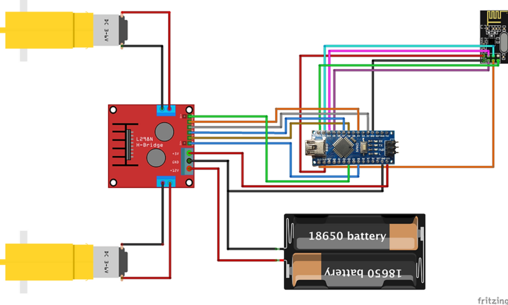
Receiver:-
TXcode.ino
//Viral Science www.viralsciencecreativity.com www.youtube.com/c/viralscience
//Joystick Car Transmitter

#include <SPI.h>
#include <nRF24L01.h>
#include <RF24.h>
RF24 radio(5,6); // CE, CSN
const byte address[6] = "00001";
char xyData[32] = "";
int joystick[2];
int buzz = 10;
void setup() {
  Serial.begin(9600);
  radio.begin();
  radio.openWritingPipe(address);
  radio.setPALevel(RF24_PA_MAX);
  radio.stopListening();
  pinMode(buzz, OUTPUT);
  digitalWrite(buzz,LOW);
}
void loop() {

  joystick[0] = analogRead(A0);
  joystick[1] = analogRead(A2);

  radio.write( joystick, sizeof(joystick) );
}
RXCode.ino
//Viral Science www.viralsciencecreativity.com www.youtube.com/c/viralscience
//Joystick Car Receiver

#include <SPI.h>
#include <nRF24L01.h>
#include <RF24.h>
#define enA A5
#define in1 6
#define in2 7
#define enB A3
#define in3 2
#define in4 4

RF24 radio(9,10); // CE, CSN
const byte address[6] = "00001";
char receivedData[32] = "";
int  xAxis, yAxis;
int motorSpeedA = 0;
int motorSpeedB = 0;
int joystick[2];

void setup() {
  pinMode(enA, OUTPUT);
  pinMode(enB, OUTPUT);
  pinMode(in1, OUTPUT);
  pinMode(in2, OUTPUT);
  pinMode(in3, OUTPUT);
  pinMode(in4, OUTPUT);
  Serial.begin(9600);
    digitalWrite(in1, LOW);
    digitalWrite(in2, LOW);
    digitalWrite(in3, LOW);
    digitalWrite(in4, LOW);
  radio.begin();
  radio.openReadingPipe(0, address);
  radio.setPALevel(RF24_PA_MAX);
  radio.startListening();


}
void loop() {

  if (radio.available()) {   // If the NRF240L01 module received data

      radio.read( joystick, sizeof(joystick) );

    radio.read(&receivedData, sizeof(receivedData));
    yAxis = joystick[0];
    xAxis = joystick[1];

    Serial.println(yAxis);
    Serial.println(xAxis);

  }

  if (yAxis < 470) {

    digitalWrite(in1, HIGH);
    digitalWrite(in2, LOW);

    digitalWrite(in3, HIGH);
    digitalWrite(in4, LOW);

    motorSpeedA = map(yAxis, 470, 0, 0, 255);
    motorSpeedB = map(yAxis, 470, 0, 0, 255);
  }
  else if (yAxis > 550) {

    digitalWrite(in1, LOW);
    digitalWrite(in2, HIGH);

    digitalWrite(in3, LOW);
    digitalWrite(in4, HIGH);

    motorSpeedA = map(yAxis, 550, 1023, 0, 255);
    motorSpeedB = map(yAxis, 550, 1023, 0, 255);
  }

  else {
    motorSpeedA = 0;
    motorSpeedB = 0;
  }

  if (xAxis > 550) {

    int xMapped = map(xAxis, 550, 0, 0, 255);

    motorSpeedA = motorSpeedA + xMapped;
    motorSpeedB = motorSpeedB - xMapped;
    // Confine the range from 0 to 255
    if (motorSpeedA < 0) {
      motorSpeedA = 0;
    }
    if (motorSpeedB > 255) {
      motorSpeedB = 255;
    }
  }
  if (xAxis < 470) {

    int xMapped = map(xAxis, 470, 1023, 0, 255);

    motorSpeedA = motorSpeedA - xMapped;
    motorSpeedB = motorSpeedB + xMapped;

    if (motorSpeedA > 255) {
      motorSpeedA = 255;
    }
    if (motorSpeedB < 0) {
      motorSpeedB = 0;
    }
  }

  if (motorSpeedA < 70) {
    motorSpeedA = 0;
  }
  if (motorSpeedB < 70) {
    motorSpeedB = 0;
  }
  analogWrite(enA, motorSpeedA); // Send PWM signal to motor A
  analogWrite(enB, motorSpeedB); // Send PWM signal to motor B
}
Link:https://dronebotworkshop.com/nrf24l01-wireless-joystick/ ,https://www.viralsciencecreativity.com/post/arduino-nrf24l01-wireless-joystick-robot-car