
ตัวต้านทานแบบปรับได้ (Adjustable Resistor)
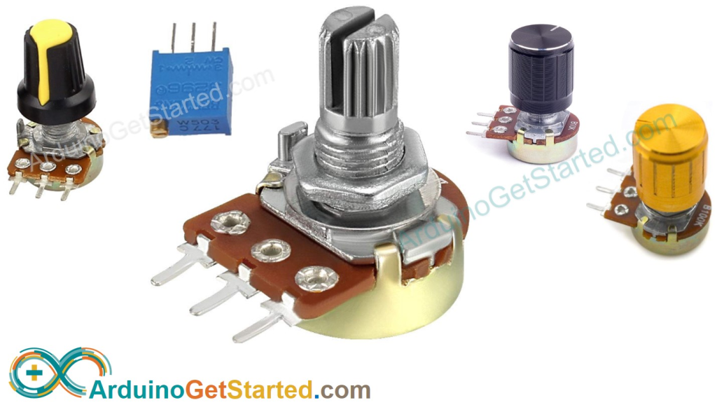
The potentiometer is a device that is used to measure the voltage or electric potential. It provides a variable resistance when the shaft of the device is turned.
Here, we will measure the amount of resistance as an analog value produced by the potentiometer. We will connect the potentiometer to the Arduino UNO board and will measure the state of the potentiometer. The required code will be uploaded from our computer to the Arduino board.
The variable resistance measured by the potentiometer can be easily read as an analog value into the Arduino board.
What is Potentiometer?
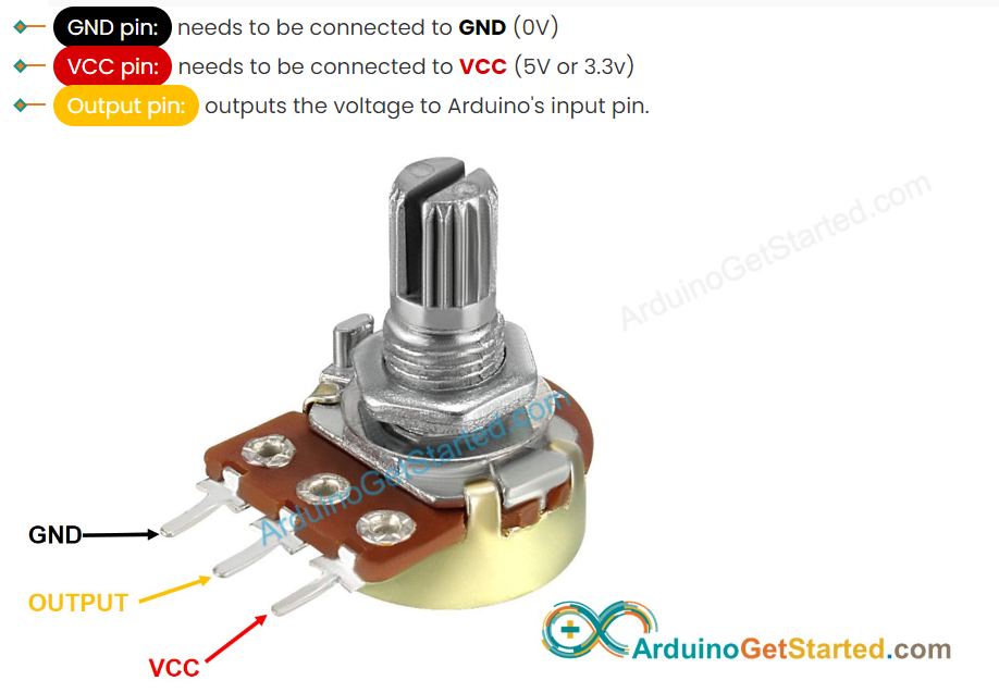
The potentiometer is a three-terminal device. It has a rotating contact that acts as an adjustable voltage divider.
The potentiometer structure consists of a sliding contact (called wiper), a resistive element, electrical terminals, and a housing.
The sliding contact moves along the resistive element, while the housing consists of the wiper and the element.
Working: The fixed input voltage is applied across the two ends terminal of a potentiometer, which further produces the adjustable output voltage at the wiper or slider.
As the slider moves from one end to another, the divider can vary the output voltage from maximum to Ground.
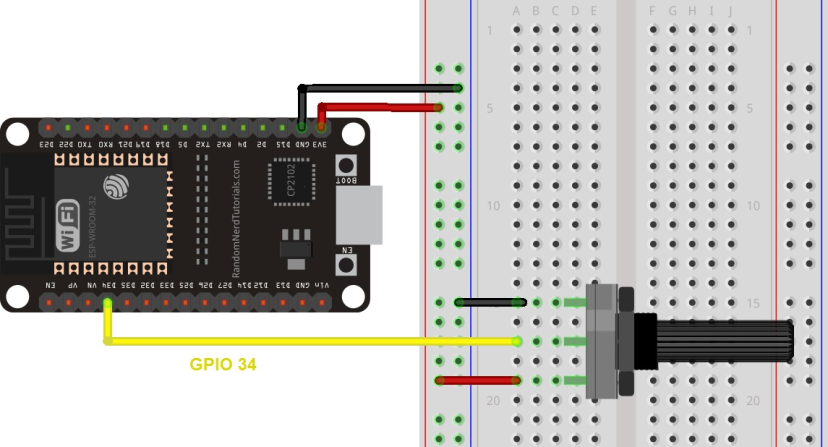
The connection of potentiometer with Arduino board is shown below:
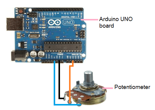
The middle terminal of potentiometer is connected to the analog pin to read the analog data.
Potentiometer with LED
In this example, we will use a potentiometer that controls the value at which LED blinks.
Hardware Required
The required components are listed below:
- 1 x red LED
- Arduino UNO R3 board
- 10K Ohm Potentiometer
- Jump wires
- 220 Ohm resistor
Connection
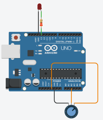
- One outer pin of the potentiometer is connected to ground (GND), and other external pin is connected to 5V of the Arduino board.
- The middle pin of the potentiometer is connected to the analog input pin A2 of the board.
- The positive terminal of the LED is connected in series with 220 Ohm resistor to pin number 13 of the board, and the negative terminal is connected to the GND.
Procedure
The analog input will turn the LED ON and OFF, which is connected to the pin number 13 of the Arduino UNO board. The time (delay time) at which LED is ON/OFF depends on the value acquired by the analogread( ).
We have connected the potentiometer to the analog pin number 2 of the Arduino UNO board.
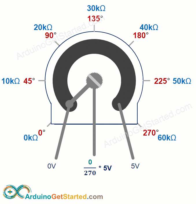
When the shaft is turned, the amount of resistance on either side of the potentiometer changes. The distance between the pin connected to 5V and GND gives the analog input. We read input 0 when the shaft is turned in one direction, while we read input 1023 when the shaft is turned in another direction.
In between the turning input between 0 and 1023, we get the desired value returned by the analogRead( ). It is proportional to the voltage being applied to the pin.
Code
We will now upload the code to the board.
The code is given below:
int potentiometerPIN = 2;
// It select the input pin connected to the middle terminal of the potentiometer
int LEDpin = 13;   // It selects the LED pin
int value = 0;       // value initialized to store the coming value from the sensor
void setup()
{
  pinMode(LEDpin, OUTPUT);  // The LED pin is declared as the output pin
}
void loop()
{
  value = analogRead(potentiometerPIN);    // It reads the value from the sensor
  digitalWrite(LEDpin, HIGH);  // turn the LEDpin ON
  delay(value);                  // delay time in milliseconds
  digitalWrite(LEDpin, LOW);   // turn the LEDpin OFF
  delay(value);
  // the delay time depends on the value stored from the sensor
}
Connection diagram
The connection diagram is shown below:
/* Learn how to use a potentiometer to fade an LED with Arduino - Tutorial
   More info and circuit schematic: http://www.ardumotive.com/arduino-tutorials/arduino-fade-led
   Dev: Michalis Vasilakis / Date: 25/10/2014                                                   */


//Constants:
const int ledPin = 13;  //pin 9 has PWM funtion
const int potPin = A2; //pin A0 to read analog input

//Variables:
int value; //save analog value


void setup(){
  //Input or output?
  pinMode(ledPin, OUTPUT);
  pinMode(potPin, INPUT); //Optional

}

void loop(){

  value = analogRead(potPin);          //Read and save analog value from potentiometer
  value = map(value, 0, 1023, 0, 255); //Map value 0-1023 to 0-255 (PWM)
  analogWrite(ledPin, value);          //Send PWM value to led
  delay(100);                          //Small delay

}
Link:https://www.javatpoint.com/arduino-potentiometer ,https://www.instructables.com/How-to-use-Potentiometer-Arduino-Tutorial/,https://arduinogetstarted.com/tutorials/arduino-potentiometer