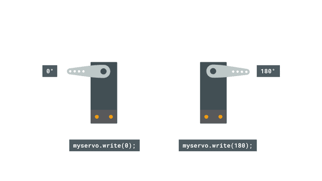
After we have successfully uploaded the code to the board, the standard servo should now start moving from 0 – 180, and then start moving from 180 – 0. This is due to the two for loops in the program, which gradually increases the
variable, which is written to the servo.
Congratulations! That was just a few easy steps to get started with standard servo motors. Now that you have this working, you can start exploring a lot of different cool projects that uses servo motors, and perhaps start making your very own robot!
#include <Servo.h>
Servo myservo;

void setup()
{
myservo.attach(9);
}
void loop()
{
myservo.write(0);
delay(1000);

myservo.write(180);
delay(1000);
}
or
#include <Servo.h>

Servo myservo;  // create servo object to control a servo
// twelve servo objects can be created on most boards

int pos = 0;    // variable to store the servo position

void setup() {
  myservo.attach(9);  // attaches the servo on pin 9 to the servo object
}

void loop() {
  for (pos = 0; pos <= 180; pos += 1) { // goes from 0 degrees to 180 degrees
    // in steps of 1 degree
    myservo.write(pos);              // tell servo to go to position in variable 'pos'
    delay(15);                       // waits 15ms for the servo to reach the position
  }
  for (pos = 180; pos >= 0; pos -= 1) { // goes from 180 degrees to 0 degrees
    myservo.write(pos);              // tell servo to go to position in variable 'pos'
    delay(15);                       // waits 15ms for the servo to reach the position
  }
}
In this tutorial we will see how do servo motors work and how to control a small size hobby servo motor with Arduino development board. We’ll also see the simulation of Arduino UNO board with a typical servo motor using Labcenter Electronics Proteus circuit simulation software.
What is a servo motor and how it works?
A servo motor is a type of electric motor that is designed for precise control of position, velocity, and acceleration. It is commonly used in applications that require accurate and controlled motion, such as robotics, CNC machines, and industrial automation.
The most used hobby servo motors are: SG90 Micro Servo and MG996R Servo.
The SG90 micro servo motor is the one used in this tutorial, it is the one shown below with horns and screws:
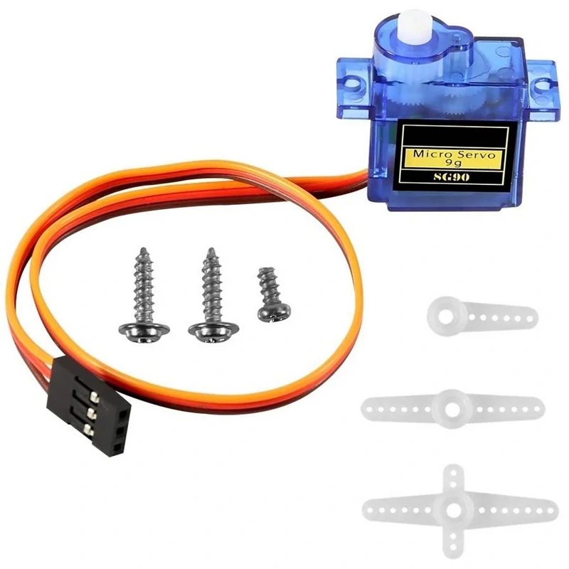
SG90 Micro servo motor specification:
| Operating Voltage | 4.8 – 6V |
| Max. Current | 600mA |
| Torque | 11 N.cm @ 4.8V 15 N.cm @ 6V |
| Speed | 0.12 sec/60° @ 4.8V 0.10 sec/60° @ 6V |
| Weight | 9 g |
The SG90 servo motor usually comes with a 3-pin connector that makes it easy to connect to a control circuit or microcontroller.The pins typically include ground (Brown wire), power supply (Red wire), and the control signal (Orange wire).
It’s important to note that there may be slight variations in specifications across different manufacturers, so it’s always a good idea to refer to the specific datasheet or documentation provided by the manufacturer for the most accurate and up-to-date information.
The key feature of a servo motor is its ability to maintain a set position even when external forces try to move it. This is achieved by using a feedback mechanism that constantly measures the motor’s actual position and compares it to a desired position. The motor’s control circuit then adjusts the motor’s position as needed to minimize the difference between the actual and desired positions.
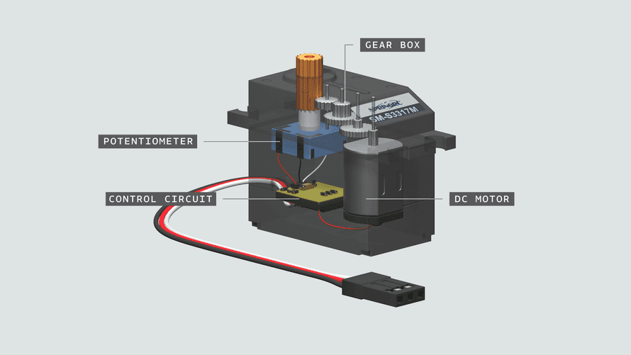
Servo motors are available in a wide range of sizes, power ratings, and performance specifications. They are typically composed of a DC motor, a control circuit, a feedback mechanism (such as a potentiometer or encoder), and a gearbox (which increases the motor’s torque and reduces its speed).
In a closed-loop circuit, the control circuit continuously measures the motor’s actual position using the position sensor and compares it to the desired position. The control circuit then calculates the error signal and adjusts the motor’s position by sending control signals to the motor. This process is repeated until the actual position of the motor matches the desired position.
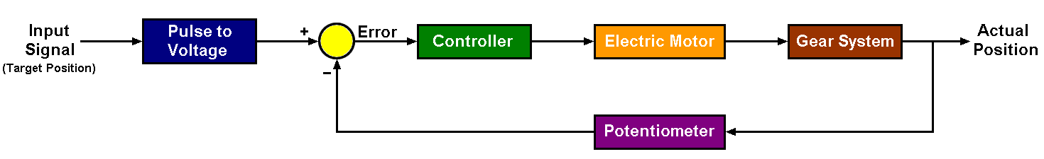
Servo motors are controlled by a series of pulses that are sent to the motor’s control circuit which is represented in the above control diagram as Input Signal (Target Position). These pulses are typically generated by a microcontroller or other type of controller.
The duration of each pulse determines the position of the servo motor’s shaft. A typical pulse width range for a servo motor is between 1 millisecond and 2 milliseconds, with a pulse width of 1.5 milliseconds representing the center position.
When servo motor control circuit receives a signal from the microcontroller system, it compares target position with actual position and generates an Error. The Error signal is sent to a Controller Circuit that controls the DC motor through H-Bridge circuit. The H-Bridge circuit allows the rotation of DC motor in both directions according to a control signals (sent by the controller circuit).
The Gear System (or gearbox) reduces the speed of the motor and increases its torque. This allows the motor to move a load with high precision and accuracy.
The amount of movement per pulse, or the resolution of the servo motor, depends on the motor’s gear reduction ratio and the number of pulses per second that are sent to the motor.
Servo motors are typically controlled using a series pulses or simply a PWM (Pulse-Width Modulation) signal.
The PWM signal is a square wave signal that varies in duration (pulse width) but has a fixed frequency. The duty cycle, which is the percentage of time the signal is high (on) during each period, determines the position of the servo motor.
A typical PWM signal for a servo motor has a frequency of 50 Hz and a pulse width range of 1 to 2 milliseconds, with a pulse width of 1.5 milliseconds representing the center position. By adjusting the duty cycle of the PWM signal, we can control the position of the servo motor very precisely.
The image below shows a simple relationship between pulse width and servo motor position:
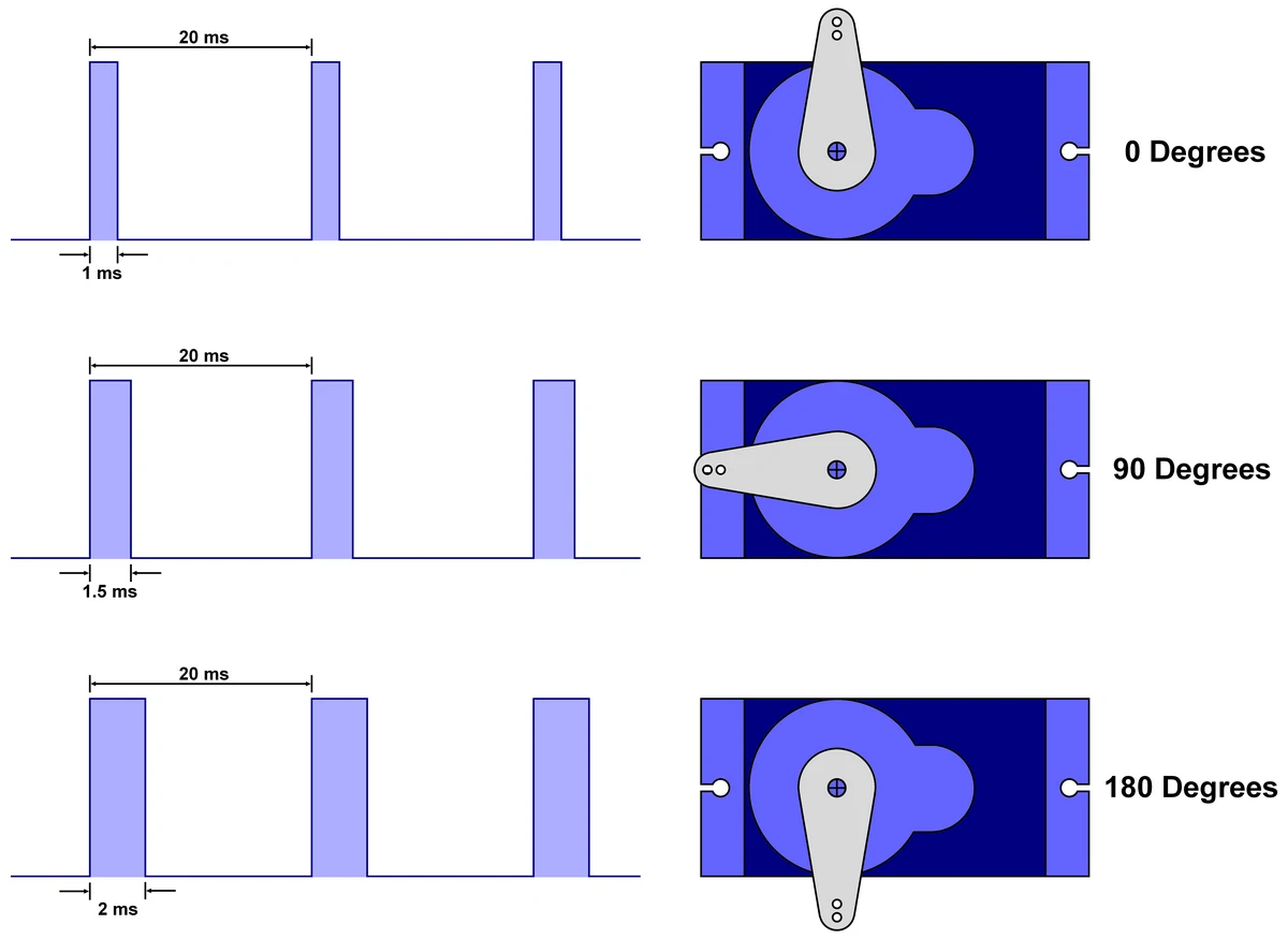
As shown above, a zero degrees is represented by a pulse width of 1 milliseconds,
A 90 degrees is the center position of the servo motor, it is represented by a pulse width of 1.5 milliseconds,
A 180 degrees is represented by a pulse width of 2 milliseconds.
This means servo motor angle position is directly proportional to the pulse width.
The following simple animation shows the relationship between servo motor angle and pulse width where pulse width varies between 1ms & 2ms.
Servo Motor Control with Arduino:
Due to its simplicity, the SG90 micro servo motor is used in this tutorial as it can be powered directly from the Arduino board.
Hardware Required:
- Arduino board
- SG90 Servo motor
- 10k Potentiometer
- Breadboard & Jumper wire
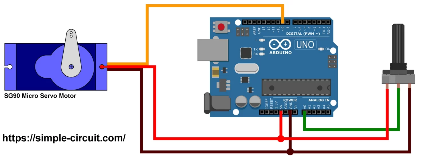
The SG90 servo motor is connected to the Arduino board as follows:
Ground pin (brown wire) is connected to Arduino GND pin.
Power supply positive terminal pin (red wire) is connected to the Arduino’s 5V pin.
Control signal pin (orange wire) is connected to Arduino digital pin 9.

A potentiometer is used to set servo’s position (angle), its output is connected to Arduino analog channel A0.
Controlling the servo motor with the potentiometer involves using the analog input of the Arduino (A0) to read the potentiometer’s position and mapping that value to control the servo motor. Therefore, the servo gets a position according to the one of the potentiometer.
One end of the potentiometer terminals is connected to 5V pin of the Arduino and the other end is connected to GND pin of the Arduino board.
Servo Motor Control with Arduino Code:
The Arduino IDE already provides a nice built-in library called “Servo” that simplifies servo motor control. This library allows the control of one or more servo motors using one Arduino board.
At the beginning of your Arduino code, the “Servo” library is included as shown below:
#include <Servo.h>   // include Arduino Servo library

Servo servo;       // create servo object to control a servo

#define PotPin    A0   // define potentiometer output pin connection
#define ServoPin  9    // define Servo control pin connection

void setup()
{

  servo.attach( ServoPin );  // attaches Servo control pin

}


void loop()
{
  uint16_t an = analogRead(PotPin);    // read analog data from potentiometer output

  uint8_t angle = map(an, 0, 1023, 0, 180);   // scale previous value between 0 and 180 (angle form)

  if ( angle != servo.read() )   // check if angle changed
    servo.write(angle);          // set new servo motor angle

  delay(10);                     // waits for the servo to get there

}
Knob
Controlling a servo position using a potentiometer (variable resistor).
#include <Servo.h>

Servo myservo;  // create servo object to control a servo

int potpin = 0;  // analog pin used to connect the potentiometer
int val;    // variable to read the value from the analog pin

void setup() {
  myservo.attach(9);  // attaches the servo on pin 9 to the servo object
}

void loop() {
  val = analogRead(potpin);            // reads the value of the potentiometer (value between 0 and 1023)
  val = map(val, 0, 1023, 0, 180);     // scale it to use it with the servo (value between 0 and 180)
  myservo.write(val);                  // sets the servo position according to the scaled value
  delay(15);                           // waits for the servo to get there
}
Sweep
Sweeps the shaft of a RC servo motor back and forth across 180 degrees.
#include <Servo.h>

Servo myservo;  // create servo object to control a servo
// twelve servo objects can be created on most boards

int pos = 0;    // variable to store the servo position

void setup() {
  myservo.attach(9);  // attaches the servo on pin 9 to the servo object
}

void loop() {
  for (pos = 0; pos <= 180; pos += 1) { // goes from 0 degrees to 180 degrees
    // in steps of 1 degree
    myservo.write(pos);              // tell servo to go to position in variable 'pos'
    delay(15);                       // waits 15ms for the servo to reach the position
  }
  for (pos = 180; pos >= 0; pos -= 1) { // goes from 180 degrees to 0 degrees
    myservo.write(pos);              // tell servo to go to position in variable 'pos'
    delay(15);                       // waits 15ms for the servo to reach the position
  }
}
Link:https://simple-circuit.com/sg90-servo-motor-control-with-arduino-proteus-simulation/,https://docs.arduino.cc/learn/electronics/servo-motors/