Introduction
In embedded audio projects, a cost-effective, easy-to-use microphone module can quickly turn ideas into reality. Whether building voice-controlled ESP32 devices, creating Raspberry Pi recording setups, or debugging audio acquisition systems, the INMP441 MEMS microphone module has become a popular choice among beginners and developers thanks to its digital output advantages and stable performance. This article will comprehensively break down the core value of this module, covering product analysis, competitor comparisons, practical tutorials, and common questions.
What is the INMP441 MEMS microphone module?
The INMP441 is an omnidirectional MEMS (Micro-Electro-Mechanical Systems) digital microphone module with a bottom sound hole design. Its core highlight is the integration of a MEMS sensor, signal conditioning circuit, analog-to-digital converter (ADC), and anti-aliasing filter, directly outputting 24-bit high-precision audio data via the I²S digital interface. No additional audio codec is required, enabling seamless connection with microcontrollers/processors such as ESP32 and Raspberry Pi, and avoiding signal interference issues common with analog microphones.
It focuses on low power consumption, high signal-to-noise ratio (SNR), and wide frequency response, capable of reproducing natural and clear sound. Meanwhile, its compact package adapts to various small device designs, widely used in video conferencing systems, smart homes, game controllers, security equipment, and other scenarios.
INMP441 vs MAX9814 vs MAX4466: A Comparison of Three Popular Microphone Modules
In the entry-level audio acquisition field, the comparison between INMP441, MAX9814, and MAX4466 is unavoidable. Although all three are commonly used microphone modules, their core designs and applicable scenarios differ significantly. Choose based on project requirements:
| Features | INMP441 | MAX9814 | MAX4466 |
|---|---|---|---|
| Output Type | Digital (I²S Interface) | Analog (Amplified Output) | Analog (Direct Output) |
| Key Advantages | No signal interference, high-precision 24-bit data | Built-in Automatic Gain Control (AGC) | Low cost, simple circuitry |
| Signal-to-Noise Ratio (SNR) | 61 dBA (High, strong noise resistance) | 60 dBA (Moderate) | 58 dBA (Moderate to low) |
| Power Consumption | Low (1.4-2.5mA) | Moderate (2.5-4mA) | Low (<1mA) |
| Ideal Use Cases | Digital audio projects, ESP32/Raspberry Pi development | Voice amplification, entry-level recording | Basic sound detection, low-budget projects |
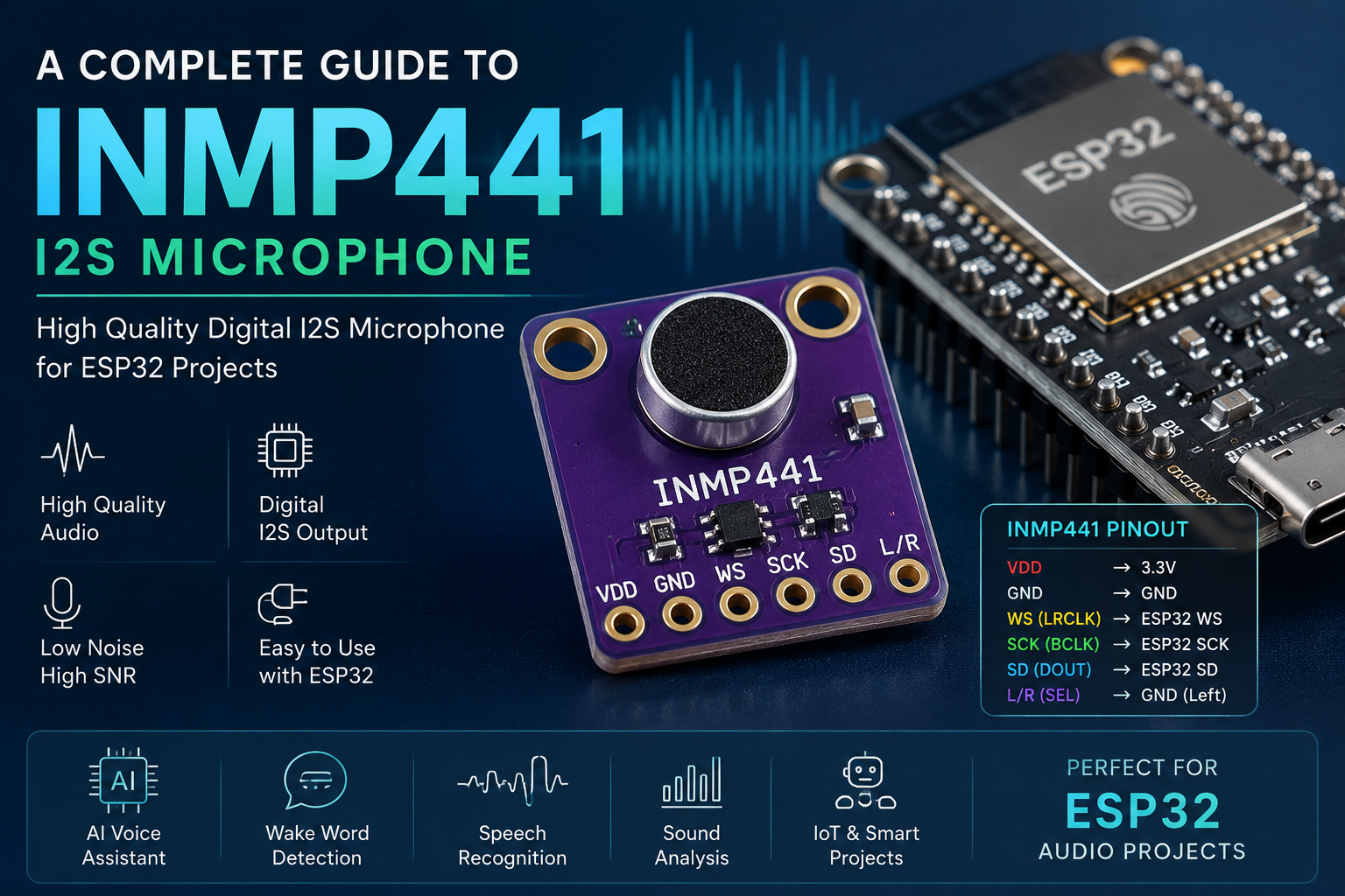
INMP441 microphone interface definition

| Pin | Description |
|---|---|
| SCK | Serial data clock for I²S interface |
| WS | Serial data word selection for I²S interface |
| L/R | Left/right channel selection. – When set to low level: Microphone outputs signal on the left channel of I²S frames. – When set to high level: Microphone outputs signal on the right channel of I²S frames |
| SD | Serial data output for I²S interface |
| VCC | Input power supply (1.8V to 3.3V) |
| GND | Power ground |
INMP441 Key Hardware Parameters
| PARAMETER | RATING |
|---|---|
| Supply Voltage (Vcc) | -0.3 V to +3.63 V |
| Digital Pin Input Voltage | -0.3 V to Vcc + 0.3 V or 3.63 V, whichever is less |
| Sound Pressure Level | 160 dB |
| Mechanical Shock | 10,000 g |
| Vibration | Per MIL-STD-883 Method 2007, Test Condition B |
| Temperature Range | Biaxed: -40°C to +85°CStorage: -55°C to +150°C |
INMP441 Datasheet
If you want to learn more NMP441 MEMS microphone module details, you can refer to this datasheet.
Application Fields
- Consumer Electronics: Adapt to smart wearables (e.g., voice control for fitness trackers), portable recording devices (paired with ESP32/Raspberry Pi), and game peripherals (VR/AR voice communication), enhancing audio interaction experience with low power consumption and high SNR.
- Smart Homes:Act as the core component for voice control terminals (smart switch/light wake-up), home security early warning (abnormal sound detection), and environmental sound monitoring (baby crying detection), enabling contactless control and safety protection.
- Industrial and IoT:Used for industrial equipment fault diagnosis (abnormal noise analysis of motors/water pumps), factory noise monitoring (over-limit alarm), and warehouse environmental early warning (abnormal sound detection in flammable material warehouses), with digital output resisting electromagnetic interference.
- Automotive Electronics:Support in-car voice assistants (central control command collection), in-car safety monitoring (child left-behind sound detection), and dashcam audio acquisition (accident sound evidence recording), with omnidirectional sound pickup adapting to multi-seat scenarios in cars.
- Medical and Health:Assist breathing monitoring equipment (sleep apnea sound analysis), rehabilitation aids (aphasia pronunciation training), and portable medical terminals (teleconsultation sound collection), with low power consumption adapting to the battery life requirements of medical devices.
- Education and Maker:Serve as a teaching tool for digital audio experiments (practical operation of I²S interface/ADC conversion principles), facilitating maker projects (sound-controlled robots) and competition development, with easy operation lowering the development threshold.
Project 1: INMP441 + Arduino Uno Simple Sound Monitor
The INMP441 MEMS microphone captures ambient sounds, converts audio signals into digital data, and displays real-time sound intensity values on the Arduino serial monitor. When the sound exceeds the preset threshold, the LED flashes to alert users, helping beginners understand the signal acquisition and basic data processing logic of digital microphones.
Material Requested
- Arduino Uno Development Board
- INMP441 MEMS Microphone Module
- LED Light
Hardware Connection Steps
Since the Arduino Uno lacks a hardware I²S interface, data transmission requires software emulation of the I²S protocol. To achieve this, digital pins on the Arduino are used instead of the dedicated I²S pins, with the wiring configuration as follows:
| INMP441 Pin | Arduino Uno Pin | Additional Notes |
|---|---|---|
| VDD | 3.3V | Power supply for the microphone (DO NOT connect to 5V, it will burn the module) |
| GND | GND | Common ground to stabilize circuit potential |
| SCK | D2 | Software-simulated I²S clock signal pin |
| WS | D3 | Software-simulated I²S channel control pin (left channel selected) |
| SD | D4 | Digital audio data output pin of the microphone |
| (Extra Circuit) LED Anode | D13 (via 1kΩ resistor) | Arduino’s built-in D13 pin can directly drive the LED |
| (Extra Circuit) LED Cathode | GND | Forms the current loop |
Software Programming
To simulate I²S by software, install the Adafruit_I2S.h library first: open Arduino IDE, click project, load library, manage library, search “Adafruit I2S”, and install the corresponding library.
Code
#include <Adafruit_I2S.h>

// 1. Define I²S pins (corresponding to hardware connections)
#define I2S_SCK 2
#define I2S_WS 3
#define I2S_SD 4

// 2. Define sound threshold and LED pin
const int soundThreshold = 500;  // Adjust based on environment (higher = more sensitive to loud sounds)
const int ledPin = 13;           // Arduino's built-in LED pin (for easy debugging)

// 3. Initialize I2S object
Adafruit_I2S i2s;

void setup() {
  Serial.begin(115200);          // Initialize serial communication at 115200 baud rate (for data display)
  pinMode(ledPin, OUTPUT);       // Set LED pin as output

  // 4. Initialize INMP441 (configure sample rate, channels, bit depth)
  if (!i2s.begin(I2S_SCK, I2S_WS, I2S_SD, I2S_NO_MCLK, 16000, 16, 1)) {
    Serial.println("INMP441 initialization failed! Please check wiring.");
    while (1);  // Halt if initialization fails, prompting user to troubleshoot
  }
  Serial.println("INMP441 + Arduino Sound Monitor started");
  Serial.print("Sound threshold: ");
  Serial.println(soundThreshold);
}

void loop() {
  int16_t audioData;  // Variable to store 16-bit audio data from microphone
  size_t bytesRead;   // Variable to store number of bytes read

  // 5. Read audio data from INMP441
  bytesRead = i2s.read(&audioData, sizeof(audioData));

  // 6. Process data: take absolute value to eliminate positive/negative signal difference
  int soundIntensity = abs(audioData);

  // 7. Display sound intensity on serial monitor (for real-time observation)
  Serial.print("Current sound intensity: ");
  Serial.println(soundIntensity);

  // 8. Sound threshold check: flash LED if intensity exceeds threshold
  if (soundIntensity > soundThreshold) {
    digitalWrite(ledPin, HIGH);  // Turn LED on
    delay(100);                  // Keep on for 100ms
    digitalWrite(ledPin, LOW);   // Turn LED off
    delay(100);                  // Keep off for 100ms (creates blinking effect)
  } else {
    digitalWrite(ledPin, LOW);   // Keep LED off if below threshold
  }

  delay(50);  // Control loop frequency to prevent serial monitor spam
}
Project 2: INMP441 + ESP32 Realize Audio Transmission
Project Goal
This tutorial demonstrates how to use the ESP32 development board with the INMP441 microphone module for audio capture, and transmit the audio data to a Windows host via UDP for playback. With simple code, you can receive and play the microphone input audio in real time.
Material Requested
- ESP32 development board
- INMP441 microphone module
- Connecting line
Hardware Connection Steps
- INMP441 VCC → ESP323.3V
- INMP441 GND → ESP32GND
- INMP441 SCK → ESP32GPIO 17
- INMP441 WS → ESP32GPIO 18
- INMP441 SD → ESP32GPIO 16
Hardware Code
#include <Arduino.h>
#include <WiFi.h>
#include <driver/i2s.h>
#include <WiFiUdp.h>

// I2S (Inter-IC Sound) pin definitions for the microphone
#define I2S_WS 18    // Word Select (LRCLK) pin
#define I2S_SD 16    // Serial Data (SDATA) pin, receives audio data from the mic
#define I2S_SCK 17   // Serial Clock (BCLK) pin
#define I2S_PORT I2S_NUM_0 // Use I2S port 0

// Audio buffer configuration
#define bufferLen 1024  // Increase buffer size to accommodate more audio data

// WiFi network credentials
const char* ssid = "YourWiFiSSID";           // Replace with your WiFi name
const char* password = "YourWiFiPassword";   // Replace with your WiFi password

// UDP server settings (where audio data will be sent)
const char* host = "ReceiverIPAddress"; // IP address of the computer/server receiving audio
const int port = 8888;                  // Port number the receiver is listening on

WiFiUDP udp;              // Create a UDP object for data transmission
int16_t sBuffer[bufferLen]; // Buffer array to hold 16-bit audio samples

void setup() {
    Serial.begin(115200);
    Serial.println("Setting up I2S...");

    // Connect to WiFi network
    setup_wifi();

    delay(1000);
    i2s_install();   // Configure and install the I2S driver
    i2s_setpin();    // Set the I2S pins
    i2s_start(I2S_PORT); // Start the I2S receiver
    delay(500);
}

void loop() {
    size_t bytesIn = 0;
    // Read audio data from the I2S buffer
    esp_err_t result = i2s_read(I2S_PORT, &sBuffer, bufferLen * sizeof(int16_t), &bytesIn, portMAX_DELAY);

    // If data was read successfully and the buffer isn't empty
    if (result == ESP_OK && bytesIn > 0) {
        // Send the audio data via UDP to the specified host and port
        udp.beginPacket(host, port);
        udp.write((uint8_t*)sBuffer, bytesIn);
        udp.endPacket();
    }
}

// Function to handle WiFi connection
void setup_wifi() {
    delay(10);
    Serial.println();
    Serial.print("Connecting to WiFi: ");
    Serial.println(ssid);

    WiFi.begin(ssid, password); // Initiate connection

    // Wait for connection to establish
    while (WiFi.status() != WL_CONNECTED) {
        delay(600);
        Serial.print("-"); // Print a dash every 600ms while connecting
    }

    // Connection successful
    Serial.println("\nWiFi connected");
    Serial.println("IP address assigned: ");
    Serial.println(WiFi.localIP()); // Print the ESP32's IP address
}

// Function to install and configure the I2S driver
void i2s_install() {
    const i2s_config_t i2s_config = {
        .mode = (i2s_mode_t)(I2S_MODE_MASTER | I2S_MODE_RX), // Set as master receiver
        .sample_rate = 16000,              // Audio sample rate (16kHz)
        .bits_per_sample = I2S_BITS_PER_SAMPLE_16BIT, // 16-bit per sample
        .channel_format = I2S_CHANNEL_FMT_ONLY_LEFT, // Use left channel only (mono)
        .communication_format = (i2s_comm_format_t)(I2S_COMM_FORMAT_STAND_I2S), // Standard I2S format
        .intr_alloc_flags = 0,             // No interrupt flags
        .dma_buf_count = 8,                // Number of DMA buffers
        .dma_buf_len = bufferLen,          // Size of each DMA buffer
        .use_apll = false                  // Do not use APLL clock
    };

    i2s_driver_install(I2S_PORT, &i2s_config, 0, NULL); // Install the driver
}

// Function to set the I2S pinout
void i2s_setpin() {
    const i2s_pin_config_t pin_config = {
        .bck_io_num = I2S_SCK,   // Bit clock pin
        .ws_io_num = I2S_WS,     // Word select pin
        .data_out_num = I2S_PIN_NO_CHANGE, // No data output needed (RX only)
        .data_in_num = I2S_SD    // Data input pin (from microphone)
    };

    i2s_set_pin(I2S_PORT, &pin_config); // Apply the pin configuration
}
Windows Host Code
Use Python to write programs:
import socket
import pyaudio

# Audio configuration settings
CHUNK = 1024  # Size of each audio packet (in frames)
FORMAT = pyaudio.paInt16  # Audio data format (16-bit integer)
CHANNELS = 1  # Single channel (mono)
RATE = 16000  # Sampling rate (16 kHz)

# Create a PyAudio object to handle audio streaming
p = pyaudio.PyAudio()

# Open an audio output stream
stream = p.open(format=FORMAT,
                channels=CHANNELS,
                rate=RATE,
                output=True) # 'output=True' indicates this is a playback stream

# Configure the UDP server
server_socket = socket.socket(socket.AF_INET, socket.SOCK_DGRAM)
# Bind the socket to all available network interfaces on port 8888
server_socket.bind(('0.0.0.0', 8888))

print("Waiting for audio data stream...")

try:
    # Continuous loop to receive and play audio
    while True:
        # Receive data from the client. The buffer size is CHUNK * 2 because each int16 sample is 2 bytes.
        data, addr = server_socket.recvfrom(CHUNK * 2)

        # If no data is received, break out of the loop
        if not data:
            break

        # Write the received audio data to the output stream for playback
        stream.write(data)

except KeyboardInterrupt:
    # Handle program termination with Ctrl+C
    pass

finally:
    # Clean up resources
    stream.stop_stream()
    stream.close()
    p.terminate()
    server_socket.close()
https://youtube.com/watch?v=fbMknk4J4H4%3Fcontrols%3D1%26rel%3D0%26playsinline%3D0%26cc_load_policy%3D0%26autoplay%3D0%26enablejsapi%3D1%26origin%3Dhttps%253A%252F%252Feasyelecmodule.com%26widgetid%3D1%26forigin%3Dhttps%253A%252F%252Feasyelecmodule.com%252Fa-complete-guide-to-the-inmp441-i2s-microphone%252F%26aoriginsup%3D1%26gporigin%3Dhttps%253A%252F%252Fwww.google.com%252F%26vf%3D1
FAQS
No data when INMP441 is connected to ESP32?
Check three points:
1.Verify if the pins are correctly connected (SCK/WS/SD pins).
2.Confirm the CHIPEN pins are set to high level.
3.Ensure stable power supply (use 3.3V instead of 5V to prevent module burnout).
Is the collected sound noisy?
Ensure a 0.1μF decoupling capacitor is connected in parallel next to the VDD pin, and the module shares a common ground with the ESP32; keep away from interference sources such as motors and wireless modules.
Can the INMP441 be directly connected to Arduino Uno?
The Arduino Uno has no hardware I²S interface, so software-simulated I²S or an expansion board is required. It is recommended to prioritize main control boards that support hardware I²S, such as ESP32/Raspberry Pi.
How to switch left/right channels?
Adjust the level of the L/R pin: low level outputs left channel, high level outputs right channel. By default, connect to GND to use the left channel.
Which is more suitable for voice recognition: INMP441 vs MAX9814?
Voice recognition has high requirements for data accuracy and noise resistance. The INMP441’s digital output has no interference, resulting in better recognition accuracy; the MAX9814 requires additional handling of analog signal interference issues.
#include <Arduino.h>
#include <driver/i2s.h>
#include <math.h>

// -----------------------------
// Pin map (ปรับตามบอร์ดของคุณ)
// -----------------------------
#define I2S_WS   15   // LRCLK / WS
#define I2S_SCK  14   // BCLK / SCK
#define I2S_SD   32   // DATA from INMP441

#define I2S_PORT I2S_NUM_0

// -----------------------------
// Audio settings
// -----------------------------
#define SAMPLE_RATE     16000
#define BUFFER_SAMPLES   1024   // 1024 samples @ 16kHz = 64 ms

// -----------------------------
// Calibration
// -----------------------------
// ค่า offset สำหรับแปลง dBFS -> dBA (ต้องคาลิเบรตจริงกับเครื่องวัดเสียงมาตรฐาน)
// วิธีเริ่มต้น:
// 1) ป้อนเสียงอ้างอิง เช่น 94 dB SPL ที่ 1 kHz
// 2) ดูค่า dBFS ที่อ่านได้
// 3) CAL_OFFSET_DB = 94.0 - measured_dBFS
//
// ตัวอย่างเช่น ถ้าอ่านได้ -26 dBFS เมื่อป้อน 94 dB SPL
// ก็จะได้ offset ประมาณ 120 dB
float CAL_OFFSET_DB = 120.0f;

// -----------------------------
// Factory / legal thresholds
// -----------------------------
const float LEGAL_TWA_LIMIT_DB = 85.0f;     // TWA 8h
const float LEGAL_CONT_LIMIT_DB = 115.0f;   // continuous steady noise

// -----------------------------
// State
// -----------------------------
int32_t samples[BUFFER_SAMPLES];

// เก็บพลังงานเสียงสะสมสำหรับคำนวณ TWA แบบง่าย
double totalEnergy = 0.0;
double totalSeconds = 0.0;

void setupI2S() {
  i2s_config_t i2s_config = {
    .mode = (i2s_mode_t)(I2S_MODE_MASTER | I2S_MODE_RX),
    .sample_rate = SAMPLE_RATE,
    .bits_per_sample = I2S_BITS_PER_SAMPLE_32BIT,
    .channel_format = I2S_CHANNEL_FMT_ONLY_LEFT, // ต่อ L/R ของ INMP441 ลง GND
    .communication_format = I2S_COMM_FORMAT_I2S,
    .intr_alloc_flags = ESP_INTR_FLAG_LEVEL1,
    .dma_buf_count = 6,
    .dma_buf_len = 256,
    .use_apll = false,
    .tx_desc_auto_clear = false,
    .fixed_mclk = 0
  };

  i2s_pin_config_t pin_config = {
    .bck_io_num = I2S_SCK,
    .ws_io_num = I2S_WS,
    .data_out_num = I2S_PIN_NO_CHANGE,
    .data_in_num = I2S_SD
  };

  esp_err_t err;

  err = i2s_driver_install(I2S_PORT, &i2s_config, 0, NULL);
  if (err != ESP_OK) {
    Serial.printf("i2s_driver_install failed: %d\n", err);
    while (true) delay(1000);
  }

  err = i2s_set_pin(I2S_PORT, &pin_config);
  if (err != ESP_OK) {
    Serial.printf("i2s_set_pin failed: %d\n", err);
    while (true) delay(1000);
  }

  i2s_zero_dma_buffer(I2S_PORT);
}

float calculateDbFSFromBuffer(const int32_t *buf, size_t n) {
  // INMP441 ส่งข้อมูล 24-bit packed ใน 32-bit word
  // มักต้องเลื่อนขวา 8 บิต เพื่อดึงค่าที่มีนัยสำคัญ
  double sumSquares = 0.0;

  for (size_t i = 0; i < n; i++) {
    int32_t s = buf[i] >> 8;  // แปลงจาก 32-bit container -> 24-bit signed-ish range
    double x = (double)s / 8388608.0; // 2^23
    sumSquares += x * x;
  }

  double rms = sqrt(sumSquares / (double)n);

  // ป้องกัน log(0)
  if (rms < 1e-9) rms = 1e-9;

  // dBFS
  float dbfs = 20.0f * log10f((float)rms);
  return dbfs;
}

float dbfsToApproxDbA(float dbfs) {
  return dbfs + CAL_OFFSET_DB;
}

void printStatus(float dbfs, float dbA, float twa8h, bool overTWA, bool overCont) {
  Serial.printf("dBFS: %7.2f | approx dBA: %7.2f | TWA(8h): %7.2f | %s | %s\n",
                dbfs,
                dbA,
                twa8h,
                overTWA ? "TWA OVER" : "TWA OK",
                overCont ? "CONT OVER" : "CONT OK");
}

void setup() {
  Serial.begin(115200);
  delay(1000);

  Serial.println();
  Serial.println("INMP441 sound level meter starting...");
  setupI2S();

  Serial.println("Tip: set INMP441 L/R = GND for mono left channel.");
  Serial.println("Tip: calibrate CAL_OFFSET_DB with a reference sound level meter.");
}

void loop() {
  size_t bytesRead = 0;

  esp_err_t err = i2s_read(
    I2S_PORT,
    (void*)samples,
    sizeof(samples),
    &bytesRead,
    portMAX_DELAY
  );

  if (err != ESP_OK || bytesRead == 0) {
    Serial.println("i2s_read failed");
    delay(500);
    return;
  }

  size_t n = bytesRead / sizeof(int32_t);
  float dbfs = calculateDbFSFromBuffer(samples, n);
  float dbA  = dbfsToApproxDbA(dbfs);

  // buffer duration in seconds
  float bufferSeconds = (float)n / (float)SAMPLE_RATE;

  // energy average for TWA/Leq
  double linear = pow(10.0, dbA / 10.0);
  totalEnergy += linear * bufferSeconds;
  totalSeconds += bufferSeconds;

  // Equivalent continuous level over the accumulated time
  double leq = 10.0 * log10(totalEnergy / totalSeconds);

  // 8-hour TWA-style interpretation for workplace comparison
  // For practical screening, use Leq from the measured period as the current indicator.
  float twa8h = (float)leq;

  bool overTWA  = (twa8h >= LEGAL_TWA_LIMIT_DB);
  bool overCont = (dbA  >= LEGAL_CONT_LIMIT_DB);

  // Print once per buffer
  printStatus(dbfs, dbA, twa8h, overTWA, overCont);

  // Optional alert
  if (overTWA) {
    Serial.println("WARNING: estimated 8h TWA is at/above 85 dBA.");
  }
  if (overCont) {
    Serial.println("DANGER: continuous level is at/above 115 dBA.");
  }
}
Link:https://easyelecmodule.com/a-complete-guide-to-the-inmp441-i2s-microphone/